Use only the power supplies with specifications recommended by the board's manufacturer. Use of any other power supply may
permanently damage the board. When power cycling the board, turn the power on or off from
the power supply, rather than removing and inserting the DC power plug on the board, to
prevent damaging the board’s power-regulation circuitry.
To connect the Honeycomb LX2:
Ensure that DIP Switch SW1 is set properly. For more information, see the Configure the board switches section in this chapter.
Insert the RAM modules to the RAM slots.
Insert the microSD card with your QNX IFS image file into the selected boot slot on the board.
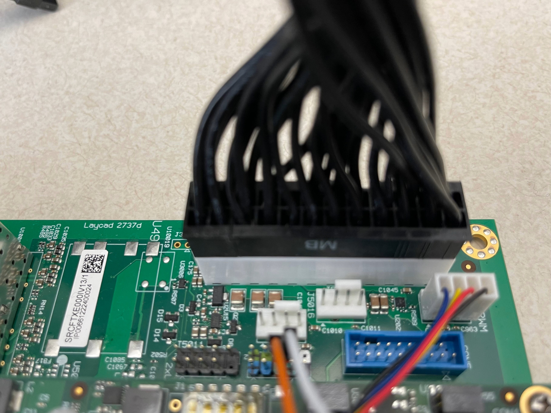
Connect the 24-pin ATX cable to the 24-pin ATX connector on the board. Then plug in the power supply.
Figure 1the 24-pin ATX connector on Honeycomb
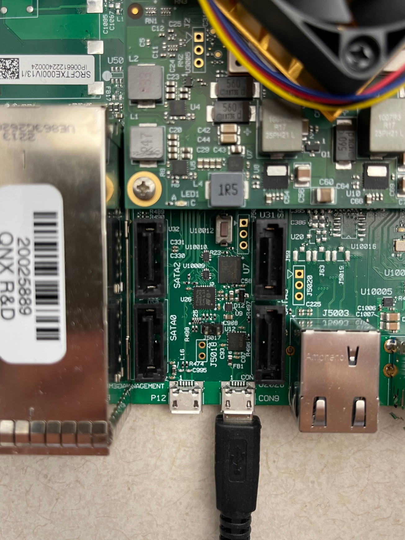
Connect the Micro USB to USB cable to the Console connector on the board.
Figure 2Serial connector for the Honeycomb
Configure the board switches
You must configure the following DIP switch for the board as follows:
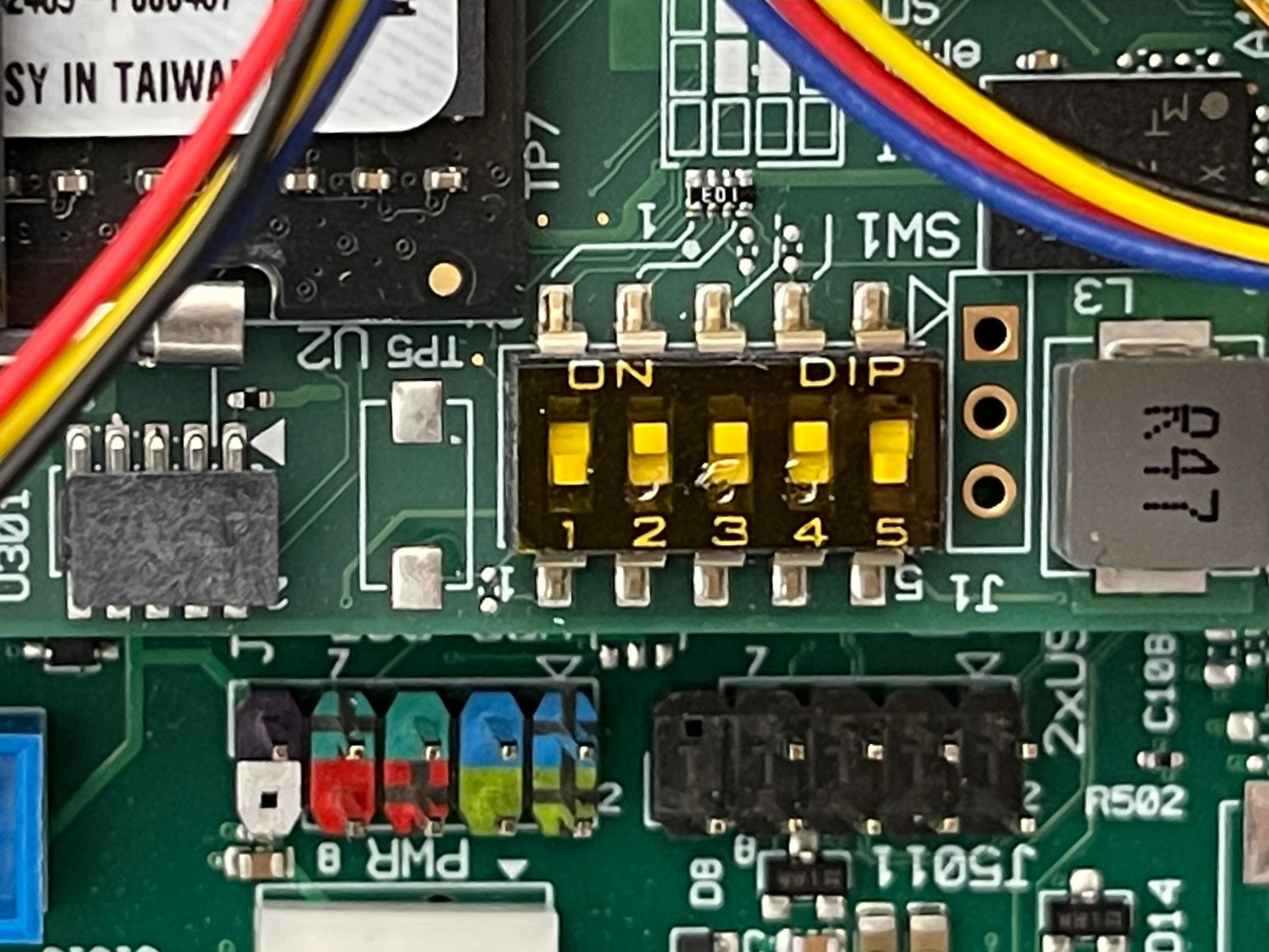
For Boot Source Selector Switch (SW1), ensure that you have the 5 DIP switches
set to these positions (listed from 1-5):
OFF ON ON ON OFF
The following diagram shows how SW1 should appear on the board:
Figure 3Boot Select Switch - SW1