Attach the USB and other cables to the appropriate hardware
connectors.
Connectors
The following ports, connectors and buttons are of most interest when you begin working with your Sitara AM62a SK board. To connect and work with the hardware, you need to do the following:
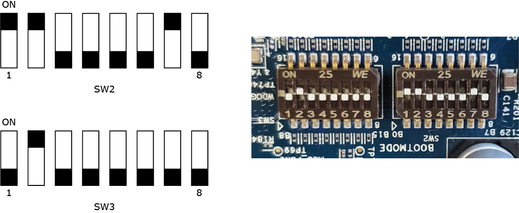
ensure that DIP Switch SW4 and SW5 are set properly. For more information, see the Configure the board switches section in this chapter.
connect a USB to serial cable to the J17 connector on the board
if you want to run graphics on your board, connect your monitor with a HDMI cable to the
corresponding port J13 on the Sitara AM62a SK board.
plug in the USB C power supply (provided separately from the board). For a list of recommended power supplies read
section 4.5.14.1 Power Requirement of the AM62a SK-EVM User's Guide that's available on the
Texas Instruments website at https://www.ti.com/lit/ug/spruj66a/spruj66a.pdf
CAUTION:
Ensure that you use the power supply that
came with your board (if applicable). Using any other power supply may
damage your board.
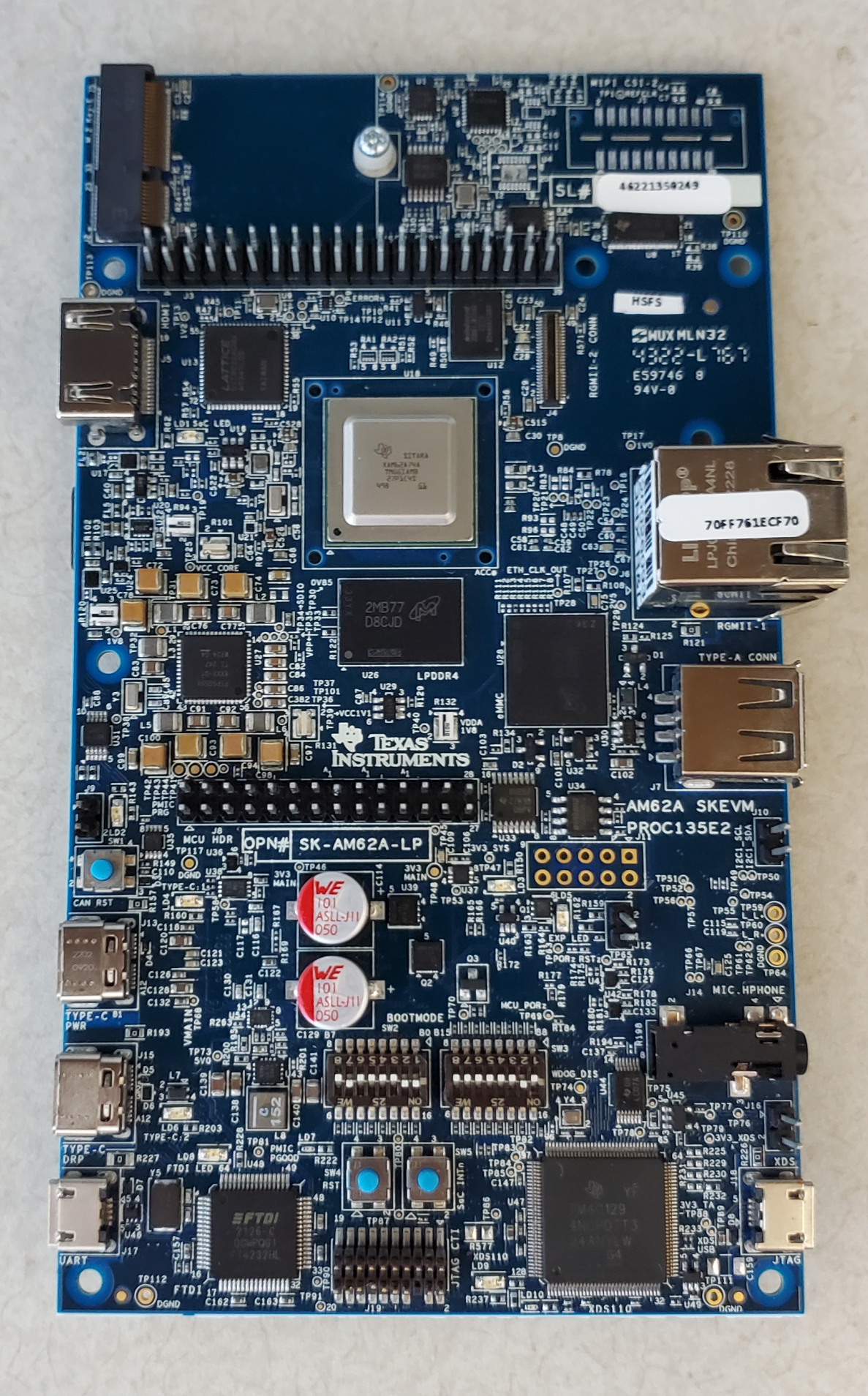
The location of the RJ45, USB-serial, and HDMI connectors are shown in the following illustration of the board:
Figure 1Connectors for the Sitara AM62a SK