Set up the hardware
Before you can work with the board, here are a few things you must do. You'll need to connect the board and set the DIP switches. For more information, see the hardware guide for the i.MX 93 EVK board on the NXP website.
Connect the hardware
- a USB 2.0 A-Male to USB Type-C cable
- an Ethernet cable
Use only the power supply provided with the board. Use of any other power supply may permanently damage the board.
To connect the i.MX 93 EVK board:
- Insert the SD with your QNX IPL, QNX IFS and DTB image files into the selected boot slot on the board (MicroSD slot).
- Connect a USB cable from the board's DEBUG UART (J1401) to the USB port on your host machine.
- Connect the Ethernet cable to the Ethernet jack on the board (J7).
- Connect a USB Type-C power supply to the PD port (J301) on the board.
- Switch Power Switch (SW301) to ON.
- Identify the host serial port on your host system:
On a Linux you can check which port is the host serial port by looking at what port appears when the cable is inserted. To do this, type the command:
$ ls /dev/ttyUSB*On a Windows system, open the Device Manager and expand the
Ports (COM and LPT)
section. Then, look for a COM port named Gadget Serial or USB Serial Port. - Connect to the COM port using your favorite
terminal program with these settings:
- Baud rate: 115200
- Data: 8 bit
- Parity: none
- Stop: 1 bit
- Flow control: none
- Serial Device: /dev/ttyUSB2
Set DIP switches on the i.MX 93 EVK board
If this is the first time you're booting the board, you need to set the boot mode switch to boot using an SD. On the i.MX 93 EVK board, the boot mode switch is SW1301. After you successfully boot the board with QNX OS, you can prepare it to boot using eMMC.
| Boot mode | Pin 1 | Pin 2 | Pin 3 | Pin 4 |
|---|---|---|---|---|
| eMMC | OFF | OFF | OFF | OFF |
| SD | OFF | ON | OFF | OFF |
| Serial Boot | ON | ON | OFF | OFF |
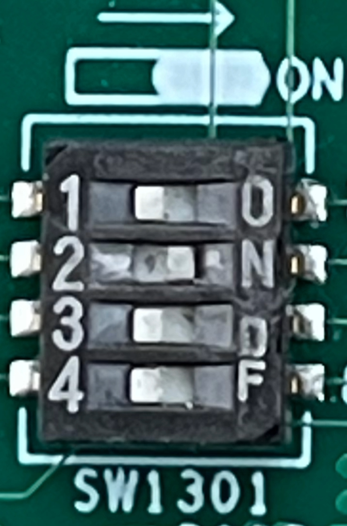
You must configure the following DIP switches for the board as follows:
ON OFF ON OFF
ON OFF ON OFF
OFF ON OFF ON
Boot from an eMMC memory device.