Connect and configure the hardware
Before you transfer your BSP to your board, you must configure the board DIP switches, and connect the board and peripherals.
Configure the board switches
ON OFF OFF OFF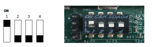
ON OFF ON ON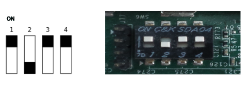
Connect the hardware
You will require a CP210x USB to UART bridge Virtual COM Port (VCP) driver on your host
development machine in order to establish a terminal session with the target over
USB. For more information, see Required Software
in the Before You Begin
chapter of this guide.
When you have the driver installed on your host, you should be able to connect to your board. To connect to your board:
Connect an RJ-45 Ethernet cable between the Ethernet port of Xilinx Zynq ZCU102 or ZCU106 and your local network.
Connect the power supply to the power connector of Xilinx Zynq ZCU102 or ZCU106.
- Connect the USB cable (included with the board) between the board's USB micro connector (J83 on the ZCU102 or ZCU106) and your host machine.
Use the board's Power on/off slider switch to power up the board.
On your host machine, determine the port name of the USB port used for serial communications with the Xilinx Zynq ZCU102 or ZCU106 board, and start your favorite terminal program with these settings:
- Baudrate: 115200
- Data: 8 bit
- Parity:none
- Stop: 1 bit
- Flow control: none