Attach the USB and other cables to the appropriate hardware
connectors.
Connectors
The following ports, connectors and buttons are of most interest when you begin working with your Jacinto 7 J722S EVM board. To connect and work with the hardware, you need to do the following:
ensure that DIP Switch SW2, SW3, SW4 is set properly. For more information, see the Configure the board switches section in this chapter.
connect a USB to serial cable to the J6 connector on the board
plug in the USB C power supply (provided separately from the board) to the J24 connector on the board. For a list of recommended power supplies read
section 2.3 Power Input of the J722SXH01EVM Evaluation Module User's Guide that's available on the
Texas Instruments website at https://www.ti.com/lit/ug/sprujb5/sprujb5.pdf
CAUTION:
Ensure that you use the power supply that
came with your board (if applicable). Using any other power supply may
damage your board.
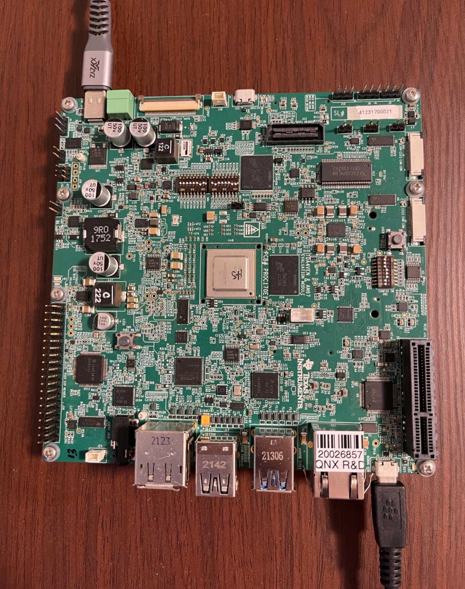
The location of the USB-serial and Power input connectors are shown in the following illustration of the board:
Figure 1Connectors for the Jacinto 7 J722S EVM