Set up the hardware
QNX Board Support Packages8.0BSP User's GuideRaspberry Pi 4B Moduleraspberrypi.orgBroadcomARM
Connect the hardware
In addition to the board, you require these cables:
- USB to TTL serial cable
- an Ethernet cable
- 5V DC power cable
CAUTION:
Use only the power supplies provided with the board. Use of any other power supply may permanently damage the board. When power cycling the board, turn the power on or off from the AC adapter side, rather than removing and inserting the DC power plug on the board, to prevent damaging the board’s power-regulation circuitry.
To connect the Raspberry Pi 4 board:
- Insert the microSD card with your QNX IFS image file into the selected boot slot on the board.
- Connect a USB to TTL serial cable from the board's serial pins and the USB port on your host machine.
Figure 1Serial pins on the 40-pin GPIO expander header (J8) 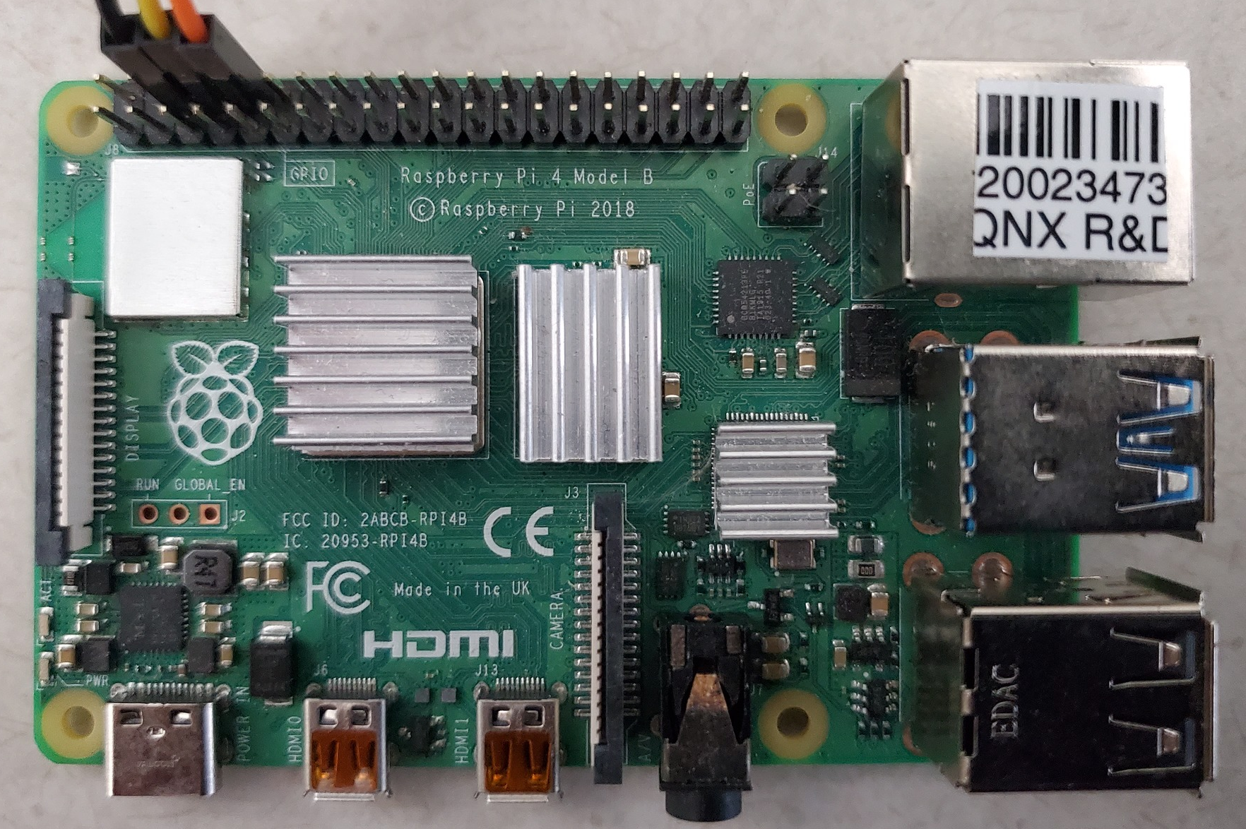
- J8 pin6: GND
- J8 pin8: GPIO14 (UART_TXD0)
- J8 pin10: GPIO15 (UART_RXD0)
- Connect the Ethernet cable to the Ethernet jack on the board.
- Connect the board's 5V DC power supply to the POWER IN (USB-C) connector on the board.
- Identify the host serial port on your host system:
On a Linux host, you can check which port is the host serial port by looking at what port appears when the cable is inserted. To do this, type the command:
$ ls /dev/ttyUSB*On a Windows system, open the Device Manager and expand the
Ports (COMand LPT)
section. Then, look for a COM port named Gadget Serial or USB Serial Port. - Connect to the COM port using your favorite terminal program with these settings:
- Baud rate: 115200
- Data: 8 bit
- Parity: none
- Stop: 1 bit
- Flow control: none
Page updated: