![[Previous]](prev.gif) |
![[Contents]](contents.gif) |
![[Index]](keyword_index.gif) |
![[Next]](next.gif) |
|
|
|
|
 |
This version of this document is no longer maintained. For the latest documentation, see http://www.qnx.com/developers/docs. |
This chapter describes how to write a graphics driver.
Before looking at the data structures and functions, it's important to understand the "big picture" for the Photon Graphics Driver Development Kit.
The purpose of the Graphics DDK is to allow third parties to write accelerated drivers without requiring QNX Software Systems to become involved in doing the work.
This section includes:
The Graphics DDK includes these sample drivers:
The Professional Edition also includes:
The 3dfx, Intel, and Chips and Technologies chipsets were chosen as the basis for the examples because the register-level programming documentation is available to anyone without signing a non-disclosure agreement.
These examples provide a good starting point for nearly any modern card. To write a new driver, you typically start with an existing driver (whichever is closest in terms of functionality to the chipset that you are targeting) and then modify the hardware-dependent pieces of the driver to drive your hardware.
Note that the driver framework includes a library called the FFB (Flat Frame Buffer). This library serves these main purposes:
For every 2D drawing entry point in a graphics driver, there's an equivalent software version in the FFB that takes identical parameters. Thus your driver isn't required to provide any functions. When the graphics framework asks your driver to supply its 2D drawing functions, the driver can return a mixture of its own accelerated functions and software-implemented FFB functions.
For more information, see "FFB library -- 2D software fallback routines" in the Libraries chapter.
Photon graphics drivers are implemented in a modular fashion. Graphics driver functionality is broken down into various groups. A graphics driver's shared object may supply one or more groups of functionality. The shared object contains one module per functional group that it implements.
A graphics driver exposes its functionality by supplying a well-known entry point per module.
The modules currently defined are:
Future modules can be implemented by defining a new well known entry point.
Because a graphics driver consists of one or more modules, it's possible to package a complete driver solution that consists of multiple shared objects. For example:
It's possible to load multiple shared objects such that there's more than one instance of a given module type. In this case, the order in which to load the shared objects can be specified to the graphics subsystem; modules found in later-loaded shared objects are used in preference to those in earlier-loaded shared objects.
With QNX Neutrino, the graphics driver subsystem consists of a main application and multiple shared objects. The main application is called io-graphics under QNX Neutrino, and is responsible for:
For more information about starting io-graphics, see the QNX Neutrino Utilities Reference.
Although the current implementation of io-graphics is limited to driving a single Photon graphical region, eventually it will simultaneously handle an arbitrary number of graphical regions and Photon servers.
There are many operations defined in the Photon high-level API that are extremely unlikely to be handled by any kind of graphics hardware. For example, a graphics card is unlikely to handle circles and scaled fonts. Even if a graphics card could handle them, it would probably draw them in a card-dependent way that would be inconsistent with other cards.
The io-graphics subsystem solves these problems by using the render library and the font manager to turn high-level entities into lower-level primitives that all hardware can draw consistently.
The font manager is obviously used for rendering any sort of text objects. It's currently designed to return raster style output that the driver draws as bitmaps or images, but eventually it will be enhanced to return vector information that future drivers could use directly.
The render library is used to simplify operations (other than fonts) that are defined in the Photon API, but that make little sense to implement in chipset-specific code. These operations include drawing circles as well as things like thick dashed lines.
The current implementation of the render library breaks down its output into scanlines, rectangles, bitmaps and images, but future plans call for it to be upgraded to return other kinds of data, such as lists of vertices representing a polygonal area to fill.
To this end, extra draw commands will be added to the 2D driver specification, but the main thing to remember is that you should have to worry only about implementing the routines currently described in this guide.
Enumeration is the process of discovering what kind of video card you have, what its capabilities are. Modeswitching is the process of putting the video card into one of its supported modes.
With a standard installation of Photon for QNX Neutrino, cards are detected with the help of a generic utility called the enumerator (enum-devices). This utility uses a mapping file to detect video chips by their PCI or AGP vendor and device IDs. Depending on what video hardware it recognizes, if any, it builds an intermediate file that's used by the crttrap utility, which is normally invoked when Photon is started, and performs the secondary phase of hardware detection. For more information about enum-devices and crttrap, see the QNX Neutrino Utilities Reference.
At the driver level, enumeration of the video modes supported by a card roughly corresponds to the VESA BIOS model. A list of numbers is returned corresponding to the modes the card can do, and a function is called for each of the mode numbers, returning information about that mode.
Switching to a given mode is accomplished by calling a driver entry point with one of the supported mode numbers.
2D drawing routines are the functions that actually produce or manipulate a two-dimensional image.
Operations that fall into this category include:
BLIT routines include operations that render an image that's in system RAM into the framebuffer and routines that move a rectangular portion of the screen from one place to another.
Offscreen memory management routines are the code that allows io-graphics to manage multiple 2D objects, or surfaces, and to use the graphics driver to draw into various surfaces, whether the surfaces are on the visible display, or not.
Offscreen memory is the most important new API feature in Photon, and is what allows applications to take advantage of more advanced hardware features.
Most modern video cards have far more memory than is actually needed for the display. Most of them also allow the graphics hardware to draw into this unused memory, and then copy the offscreen object onto the visible screen, and vice-versa.
The offscreen management module deals with managing this memory. The routines in this module deal with allocating and deallocating 2D surfaces.
Video overlay control routines manage the process of initializing and using video overlay hardware to do things like show MPEG content.
A video overlay scaler is a hardware feature that allows a rectangular area of the visible screen to be replaced by a scaled version of a different image. The prescaled video frames are typically stored in offscreen memory, and are fetched from memory and overlaid on top of the desktop display image in real time, by the overlay scaler.
Chroma keying is used to control what parts of the video frame are visible. Typically, the application picks a color to be the chroma-key color and draws a rectangle of this color where video content is to appear. When another application's window is placed on top of the video playback application, the chroma-colored rectangle is obscured. Since the video hardware is programmed to display video content only where the chroma-key color is drawn, video doesn't show through where the chroma-colored rectangle is obscured.
Most of the routines in this module deal with letting applications know what kind of features the particular hardware supports and then setting the overlay up to cover a specific area of the screen and to accept an input stream of a particular size.
The rest of the overlay routines deal with implementing a protocol so that the application knows when a given frame has been dealt with and when it can send new frames to be displayed.
Some display controllers allow you to transparently overlay multiple "screens" on a single display. Each overlay is called a layer. Layers can be used to combine independent display elements. Because overlaying is performed by the graphics hardware, this can be more efficient than rendering all of the display elements onto a single memory surface. For example, a fast navigational display can be implemented with the scrolling navigational map on a background layer and pop-up GUI elements, such as menus or a web browser, on the foreground layer.
Layer capabilities vary, depending on the display controller and the driver. Some display controllers don't support layers. Different layers on the same display may have different capabilities. Layers are indexed per display, starting from 0, from back to front in the default overlay order.
The image on a layer is fetched from one or more offscreen contexts, also called surfaces. The layer format determines the number of surfaces needed by a layer. For excample, a layer whose format is DISP_LAYER_FORMAT_ARGB888 requires one surface, while a layer whose format is DISP_LAYER_FORMAT_YUV420 requires three surfaces for a complete image.
The source viewport defines a rectangular window into the surface data. This window is used to extract a portion of the surface data for display by the layer. The destination viewport defines a rectangular window on the display. This window defines where the layer displays its image. Scrolling and scaling (if supported by the layer) can be implemented by adjusting these viewports.
You must include the file <display.h>, which contains structures that you use to bind your driver to the graphics framework.
The graphics framework binds your graphics driver by calling dlopen() to load your driver, and then finding your entry point(s). The name of the entry point depends on which functional module(s) your shared object is providing; a single shared object can provide more than one functional block, hence the names are unique. The following table applies:
| Functional block | Name of function |
|---|---|
| Core 2D drawing functions | devg_get_corefuncs() |
| Context 2D drawing functions | devg_get_contextfuncs() |
| Miscellaneous 2D drawing functions | devg_get_miscfuncs() |
| Modeswitcher and layer control | devg_get_modefuncs() |
| Memory manager / frame buffer | devg_get_memfuncs() |
| Video overlay | devg_get_vidfuncs() |
| Video capture | devg_get_vcapfuncs() |
 |
The three functions, devg_get_miscfuncs(), devg_get_corefuncs(), and devg_get_contextfuncs() must be supplied in the same shared object -- they constitute one group. |
All the functions in the table have a similar structure: the graphics framework passes to each a pointer to a disp_adapter_t structure, a pointer to a set of functions (the type of which depends on the function being called), and a table size in tabsize (plus other arguments as appropriate).
The disp_adapter_t structure is the main "glue" that the graphics framework uses to hold everything together. It describes the adapter for the graphics hardware.
Your function is expected to fill the function table with all the available functions -- this is how the graphics framework finds out about the functions supported by each functional block module.
Finally, the table size (tabsize) parameter indicates the size of the structure, in bytes. This is so that your initialization function doesn't overwrite the area provided. You should use the DISP_ADD_FUNC() macro (defined in <display.h>) to add function pointers to the tables; it automatically checks the tabsize parameter.
The idea is that newer drivers that supply more functions will run properly with older versions of Photon that supply smaller function tables.
For more information, see the Graphics Driver API chapter.
The graphics framework calls your driver's functions as follows:
modeswitch->init ();
    modeswitch->set_mode ();
    mem->init ();
        misc->init ();
            ...
            // graphics functions get called here
            ...
            // user requests a new mode; shut everything down
        misc->fini ();
    mem->fini ();
    // at this point no more graphics functions will be called

    modeswitch->set_mode ();
    mem->init ();
        misc->init ();
            ...
            // graphics functions get called here
            ...
            // shutdown of graphics drivers requested here
        misc->fini ();
    mem->fini ();
    // at this point no more graphics functions will be called
modeswitch->fini ();
|
You can call the devg_get_* functions at any time. |
Before looking at the function descriptions, there are some conventions that you should be aware of.
This section includes:
RGB colors that are passed to 2D drawing functions are in the same pixel format as the surface that's the target of the rendering operation.
However, chroma-key colors are passed with the 24-bit true-color value stored in the least significant three bytes. However, if the target of the draw operation is a palette-based surface, the palette index that corresponds to the color-key value is also stored in the most significant byte.
The coordinate (0, 0) is the top left of the displayed area. Coordinates extend to the bottom right of the displayed area. For example, if your graphics card has a resolution of 1280 (horizontal) by 1024 (vertical), the coordinates are (0, 0) for the top left corner, through to (1279, 1023), for the bottom right.
The graphics framework passes only sorted coordinates to your driver. For example, if a draw-span function is called to draw a horizontal line from (x1, y) to (x2, y), the graphics framework always passes the coordinates such that x1 <= x2; it never passes them such that x1 > x2.
All coordinates given are inclusive, meaning, for example, that a call to draw a line from (5, 12) to (7, 12) shall produce three pixels (that is, (5, 12), (6, 12), and (7, 12)) in the image, and not two. Be careful to avoid this common coding mistake:
...

// WRONG!
for (x = x1; x < x2; x++) {
...
and instead use:
...

// CORRECT!
for (x = x1; x <= x2; x++) {
...
Core 2D drawing functions are typically expected to perform very simple operations. With the exception of pattern information, and information regarding the surface that's being drawn to, the core functions can ignore most of the information in the draw context structure.
Context 2D drawing functions are expected to be able to handle more complex operations, such as chroma-keying, alpha-blending, and complex raster operations.
Core functions may be coded to handle a single pixel format. However, context functions must be prepared to handle drawing to any of the possible drawable surface types.
Another difference is that the context functions are allowed to make calls to core drawing functions, but not the other way around. The draw state structure contains a pointer to the function table that contains pointers to the core functions, which allows the context functions access to the core functions.
Since context functions can be expected to perform complex operations, it often makes sense to perform the operation in multiple stages. Future optimizations in the FFB may entail having the FFB versions of the context functions making calls to the core functions.
The graphics framework passes to every function, as its first argument, a pointer to a disp_draw_context_t structure that gives the function access to the draw state context block.
|
If your functions modify any of the context blocks during their operation,
they must restore them before they return.
If the graphics framework modifies the context blocks between calls to the draw functions, it then calls the appropriate update_*() function to inform you which parts of the context data have been modified. The graphics framework doesn't modify the context blocks while your function is running. |
When a 2D draw function (i.e. a function that's been supplied by the driver in either the disp_draw_corefuncs_t or the disp_draw_contextfuncs_t structure) is called, it's expected to perform the draw operation correctly before returning (i.e. it may not fail).
The FFB (Flat Frame Buffer) library serves as a reference as to how 2D primitives are to be rendered. The draw functions that your driver supplies in its devg_get_corefuncs() and devg_get_contextfuncs() entry points are expected to carry out the draw operation as the FFB does.
With typical graphics hardware, not all primitives can be rendered using hardware, while producing the same resulting pixels in the targeted draw surface as the FFB does. In order to perform the draw operation correctly, it's often necessary to call the FFB library functions to carry out a draw operation. This is called falling back on software.
Falling back on software can be achieved in these ways:
This has pleasant implications for the driver writer: it means that none of the draw functions are mandatory, that is, the driver implementor can simply supply only FFB functions. Obviously this would lead to a far-from-optimal driver, since none of the draw functions would be taking advantage any hardware acceleration features.
Or:
Typically, the devg_get_corefuncs() and devg_get_contextfuncs() routines function as follows:
Using the above method makes your driver forward-compatible with future versions of the driver framework. If more draw functions are added to the specification, io-graphics will pass in a larger structure, and an updated FFB library will fill in software versions of the new functions. The graphics driver doesn't need to be rebuilt or reshipped. At your discretion, you can update the graphics driver to supply accelerated versions of the new functions.
When a driver function is called to perform a draw operation, it typically checks members of the draw context structure, in order to determine if it needs to fallback on software. However, note that anytime the framework changes the draw context structure, it notifies the driver by means of one of the update-notification entry points.
As an optimization, your driver can perform these checks in its update() function (e.g. the disp_draw_contextfuncs_t's update_rop3() function) and set flags to itself (in its private context structure) that indicate whether or not it can render various graphics primitives without falling back on software. This saves each and every context function from having to perform this work at runtime; it just checks the flags in a single test.
Patterns are stored as a monochrome 8*8 array. Since many of the driver routines work with patterns, they're passed in 8-bit chunks (an unsigned char), with each bit representing one pixel. The most significant bit (MSB) represents the leftmost pixel, through to the least significant bit (LSB) representing the rightmost pixel. If a bit is on (1), the pixel is considered active, whereas if the bit is off (0), the pixel is considered inactive. The specific definitions of active and inactive, however, depend on the context where the pattern is used.
As an example, the binary pattern 11000001 (hex 0xC1) indicates three active pixels: the leftmost, the second leftmost, and the rightmost.
Note that functions that have 8x1 in their function names deal with a single byte of pattern data (one horizontal line), whereas functions that have 8x8 in their function names deal with an 8 by 8 array (eight horizontal lines).
The pattern is circular, meaning that if additional bits are required of the pattern past the end of the pattern definition (for that line) the beginning of the pattern (for that line) is reused. For example, if the pattern is 11110000 and 15 bits of pattern are required, then the first eight bits come from the pattern (i.e. 11110000) and the next 7 bits once again come from the beginning of the pattern (i.e. 1111000) for a total pattern of 111100001111000. See "Pattern rotation," below for more details about the initial offset into the pattern buffer.
A similar discussion applies to the vertical direction: if an 8-byte pattern is used and more pattern definitions are required past the bottom of the pattern buffer, the pattern starts again at the top.
In order to ensure a consistent look to anything that's drawn with a pattern, you need to understand the relationships among the x and y coordinates of the beginning of the object to be drawn, the origin of the screen, and the pat_xoff and pat_yoff members of the disp_draw_contextfuncs_t context structure.
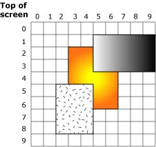
Three surfaces.
The diagram above shows three overlapping rectangles, representing three separate regions (for example, three pterm windows). If an application draws three rectangles within one Photon region, it's up to the application to draw the three rectangles in the appropriate order -- the discussion here about clipping applies only to separate regions managed by Photon.
If only the middle rectangle is present (i.e. there are no other rectangles obscuring it), your function to draw a rectangle with a pattern (e.g. draw_rect_pat8x8()), is called once, with the following parameters:
| Parameter | Value |
|---|---|
| x1 | 3 |
| y1 | 2 |
| x2 | 6 |
| y2 | 6 |
| pat_xoff | 0 |
| pat_yoff | 0 |
Note that the x1, y1, x2 and y2 parameters are passed to the function call itself, while the pat_xoff and pat_yoff parameters are part of a data structure that the function has access to.
The values for x1, y1, x2 and y2 are reasonably self-explanatory; draw a rectangle from (x1, y1) to (x2, y2). The pat_xoff and pat_yoff values are both zero. This indicates that you should begin drawing with the very first bit of the very first byte of the pattern. If the pattern looks like this:
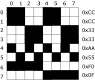
Typical pattern.
then the rectangle drawn looks like this:
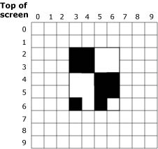
Pattern filling a surface.
If the values of the pat_xoff and pat_yoff arguments are anything other than zero (specifically, if these variables are functions of the location of the rectangle) then the pattern appears to creep along with the change of the location.
In the case where the other two rectangles are partially obscuring the rectangle of interest, Photon automatically transforms the single middle rectangle into a set of three rectangles, corresponding to the area that's still visible (this is called clipping):
This means that draw_rect_pat8x8() is called three times with these parameters:
| Parameter | First call | Second | Third |
|---|---|---|---|
| x1 | 3 | 3 | 5 |
| y1 | 2 | 4 | 5 |
| x2 | 4 | 6 | 6 |
| y2 | 3 | 4 | 6 |
| pat_xoff | 0 | 0 | 2 |
| pat_yoff | 0 | 2 | 2 |
Notice how the pat_xoff and pat_yoff pattern offset values are different in each call (first (0, 0), then (0, 2) and finally (2, 2)) in order to present the same window on the pattern regardless of where the rectangle being drawn begins. This is called pattern rotation.
To find the right bit in the pattern for a rectangle at point (X, Y):
x_index = (x + pat_xoff) % 8;
y_index = (y + pat_yoff) % 8;
The BLIT functions take a dx and dy parameter, so you should substitute that in the equations above.
The pixel formats are defined below.
|
You aren't expected to be able to render into the formats tagged with an asterisk (*) -- these can only act as sources for operations, not as destinations. Therefore, these formats are never specified as parameters to devg_get_corefuncs(). |
In any case, if you receive a pixel_format that you don't know what to do with (or don't want to handle yourself), simply call ffb_get_corefuncs() to populate the function table with software rendering routines.
For RGB formats, the name indicates the layout of the color components. For example, for DISP_SURFACE_FORMAT_ARGB1555, the Alpha bit is stored in the most significant bit of the pixel, and the Blue component is stored in the least significant 5 bits.
You can use the DISP_BITS_PER_PIXEL() and DISP_BYTES_PER_PIXEL() macros in <display.h> to determine the number of bits or bytes of a packed surface format, including packed RBG and packed YUV format.
|
These macros don't work for planar formats. Before using them, you should examine their definitions in <display.h> to see exactly what they do! |
The pixel formats for layers are defined below.
|
|
|
|