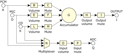
This section describes the mixer architecture.
You can usually build an audio mixer from a relatively small number of components. Each of these components performs a specific mixing function. A summary of these components or elements follows:
- Input
- A connection point where an external analog signal is brought into the mixer.
- Output
- A connection point where an analog signal is taken from the mixer.
- ADC
- An element that converts analog signals to digital samples.
- DAC
- An element that converts digital samples to analog signals.
- Switch
- An element that can connect two or more points together. A simple switch may be used as a mute control. More complicated switches can mute the channels of a stream individually, or can even form crossbar matrices where n input signals can be connected to n output signals.
- Volume
- An element that adjusts the amplitude level of a signal by applying attenuation or gain.
- Accumulator
- An element the adds all signals input to it and produces an output signal.
- Multiplexer
- An element that selects the signal from one of its inputs and forwards it to a single output line.
By using these elements you can build a simple sound card mixer:
 Figure 1. A simple sound card mixer.
In the diagram, the mute figures are switches, and the MIC and CD are input elements. This diagram is in fact a simplified representation of the Audio Codec '97 mixer, one of the most common mixers found on sound cards.
It's possible to control these mixer elements directly using the snd_mixer_element_read() and snd_mixer_element_write() functions, but this method isn't recommended because:
- The arguments to these functions are very dependent on the element type.
- Controlling many elements to change mixer functionality is difficult with this method.
- There's a better method.
The element interface is the lowest level of control for a mixer and is complicated to control. One solution to this complexity is to arrange elements that are associated with a function into a mixer group. To further refine this idea, groups are classified as either playback or capture groups. To simplify creating and managing groups, a hard set of rules was developed for how groups are built from elements:
- A playback group contains at most one volume element and one switch element (as a mute).
- A capture group contains at most one each of a volume element, switch element (as a mute), and capture selection element. The capture selection element may be a multiplexer or a switch.
If you apply these rules to the simple mixer in the above diagram, you get the following:
- Playback Group PCM
- Elements B (volume) and C (switch).
- Playback Group MIC
- Elements E (volume) and F (switch).
- Playback Group CD
- Elements L (volume) and M (switch).
- Playback Group MASTER
- Elements H (volume) and I (switch).
- Capture Group MIC
- Element N (multiplexer); there's no volume or switch.
- Capture Group CD
- Element N (multiplexer); there's no volume or switch.
- Capture Group INPUT
- Elements O (volume) and P (switch).
In separating the elements into groups, you've reduced the complexity of control (there are 7 groups instead of 17 elements), and each group associates well with what applications want to control.