Follow the instructions and illustrations below to set up a Freescale i.MX6Q SABRE Smart board with a Gemalto cellular modem and WiLink8 Wi-Fi module.
The following picture shows the hardware configuration:
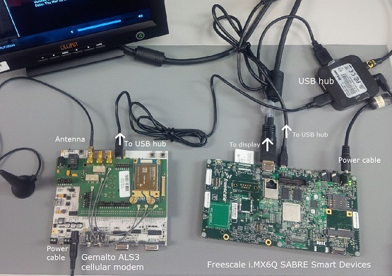 Figure 1. Freescale i.MX6Q SABRE Smart board, a powered USB hub, and a Gemalto ALS3-US cellular modem.
To set up the i.MX6Q SABRE Smart board with the Gemalto cellular modem:
- Connect the i.MX6Q board to a USB hub via the micro USB port. The board must be connected as the USB host because it controls communication in the USB link.
- Connect the Gemalto cellular modem to the USB hub via the micro USB port. The modem must be connected as the USB device because it acts as the worker in the link, servicing host requests.
Connect the WiLink 8 module to your main board.
The image below shows an i.MX6Q SABRE Smart board connected to the WiLink 8 SDMMC adapter board (WL18xxCOM82SDMMC) via SD connector 2 (J500) on the Smart Devices board and the white ribbon cable (J13).
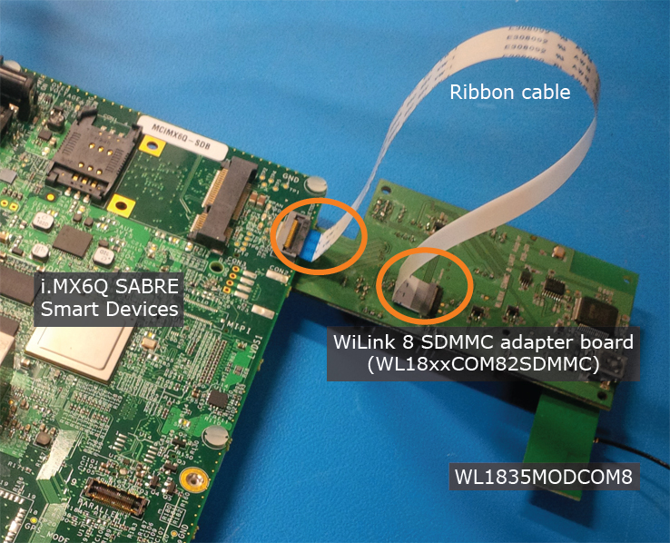 Figure 2. Close up of TI WiLink 8 Wi-Fi module and adapterNote: You must install the ribbon as shown above, so that the ribbon end inserted into the SABRE Smart board has its contact face DOWN (which means the blue tape faces UP) while the ribbon end inserted into the WiLink module has its contact face UP (which means the blue tape faces DOWN). If you don't connect the ribbon this way, the driver won't be able to reset the Wi-Fi chip on the Wi-Fi module after a warm restart, which occurs when the user issues the shutdown command to restart the system.
To enable Wi-Fi on the i.MX6Q SABRE Smart board, you must populate R212 and R213. Both components are on the front of the board near J13, as shown in the diagram below.
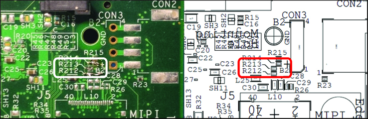 Figure 3. On the i.MX6Q SABRE Smart board, R212 and R213 must be populated to enable Wi-Fi.
- Connect the display to the i.MX6Q board and to the USB hub. The display must be connected as the USB device because it acts as the worker in the USB link, servicing host requests.
- Ensure that all peripherals are connected to power sources. Don't connect the power to the i.MX6 board yet.
- Follow the instructions in QWF Reference Images to transfer a reference image and boot the board.
For information about the locations of ports, settings for switches, etc. on your board, see the manufacturer's documentation, and the QNX BSP User's Guide for your board.