Due to the different board architectures and processes handled by the board firmware, IPLs for x86 and ARM platforms are very different.
Despite their differences, IPLs for all board families have completed their work when they have loaded the IFS image into memory and jumped to the OS startup code. They all have at least the following in common:
- They are the first software code to execute on the board (as opposed to the BIOS or Boot ROM code, which is in the board firmware).
- They finish up by handing control to the OS kernel startup code (see the Startup Programs chapter).
The figure below shows, at a high level, the sequence of components that initialize and boot a board. This process differs greatly between x86 boards and ARM boards. Even though the startup code is different on the different boards, this code is considered the point of convergence, because it is the first OS code to run. The sequence for ARM shows a Boot ROM, but some boards do not use Boot ROM or use a first-stage, low-level Boot ROM.
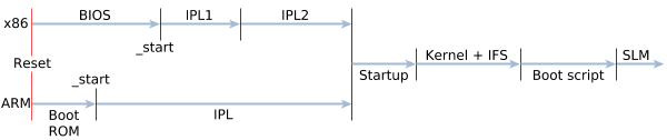 Figure 1. The boot processes for x86 and ARM platforms.
In the diagram above, the files with the first code to be executed are called _start for both the x86 board the ARM board.
The linker file
For both x86 and non-x86 boards, the file with the assembly code at the reset vector is specified in the linker file (e.g., qnx-x86.lnk or qnx-arm.lnk). For example, assuming that the QNX ARM Estragon board is 32-bit little endian, qnx-arm-board_name.lnk might begin as follows:
TARGET(elf32-littlearm)
OUTPUT_FORMAT(elf32-littlearm)
ENTRY(_start-arm-board_name)
MEMORY
{
    stack_top      :    ORIGIN = 0x402f93FC,    LENGTH = 0x0
    stack_space    :    ORIGIN = 0x402f7400,    LENGTH = 0x2000
    ram            :    ORIGIN = 0x402f0400,    LENGTH = 0x7000

    /* TLB table must be aligned to 16K (0x4000) */
    tlb         :   ORIGIN = 0x40310000,    LENGTH = 0x4000

    /* dedicated for non-cacheble buffer */
    scratch     :   ORIGIN = 0x80000000,    LENGTH = 0x100000

}

SECTIONS
{
    .text : {
            _start.o(.text)
            *(.text)
            ...