A QNX Neutrino system boot involves, in sequence, the IPL, the startup script, the OS, and, optionally, resource managers such as device drivers or utilities such as SLM.
Components
A QNX Neutrino boot sequence has three main components. Following the hardware initialization, which is often handled by a boot loader (e.g., BIOS or UEFI for x86, U-Boot for ARM), the QNX boot uses:
- an Initial Program Loader (IPL)
- a startup program
- an OS image
Both the startup program and the OS image are presented in an image filesystem (see “Image filesystem (IFS)” in this chapter).
A useful way to think about the boot process and its components is that each step provides greater abstraction from the hardware. The IPL is specific to an architecture, board, and sometimes even board revision. The startup code is specific to an architecture and board. And, generally speaking, an OS kernel can work with different boards that share an architecture.
Tasks
The figure below shows a more detailed view of the boot tasks, which includes the tasks handled by the hardware, and those that happen after the OS has started (such as launching an application). With the exception of the tasks that the hardware and firmware control, you can control the entire boot sequence, including tasks that happen after the OS has started and applications are launched.
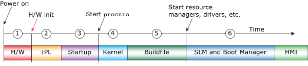 Figure 1. A high-level view of the boot sequence for a QNX Neutrino
system. The circled numbers in the diagram correspond to the steps in the boot
sequence described below.
Figure 1. A high-level view of the boot sequence for a QNX Neutrino
system. The circled numbers in the diagram correspond to the steps in the boot
sequence described below.When a QNX Neutrino system starts up, components in the system perform the following tasks. The numbers below correspond to the circled numbers in the figure above:
- The board hardware and firmware perform checks and initialization tasks, then hand control over to the software located at a predetermined location.
-
Traditionally, the location where the processor begins execution has been a hard-coded address, know as the reset vector. However, some boards support using a component such as a ROM monitor or MLO to identify where the processor should begin execution after the hardware- and firmware-controlled tasks are complete.
The IPL performs the minimum hardware configuration needed to create an environment that will allow the startup program and the QNX Neutrino kernel to run, then locates and loads the image filesystem (IFS), and transfers control to the startup program in the image (see “Image filesystem (IFS)”).
The startup program configures the system, including timers, interrupt controllers, and cache controllers (see “Startup programs” in this chapter, and the Startup Programs chapter).
When it has completed the configuration, the startup program transfers control to the OS kernel (procnto).
The OS kernel is included in the procnto module, which combines the kernel and process manager. This module sets up the kernel, then runs the instructions specified in a buildfile: a boot script that contains startup instructions for drivers and other processes, and any additional commands for running other required components.
The buildfile specifies the remainder of the boot process, including:
- the files and commands to include in the image
- the startup order for the executables
- the loading options for the files and the executables
- the command-line arguments and environment variables for the executables
The buildfile may specify most or all applications that will run on the system, or include only a few applications, leaving the majority to be started later.
When all the commands in the buildfile have completed successfully, the QNX system has finished booting (see the OS Image Buildfiles chapter).
- The System Launch and Monitor (SLM) utility is used to launch complex applications consisting of many processes that must be started in a specific order. It allows you to configure application launch sequences without modifying the buildfile (see “System Launch and Monitor (SLM)”).
On ARM platforms, the reset vector is normally at address 0x00000000, so the boot device (NOR flash or other first-stage boot device) is mapped to this physical address. On x86 platforms, the reset vector is usually at 0xFFFFFFF0. Some boards support retrieving the execution entry point from a component such as a ROM monitor or a Multimedia card LOader (MLO).