Another design consideration was the shared memory driver and the layout of the shared memory. We'll see the details when we look at the adios server itself.
The shared memory design involved setting up the layout of the data areas, as well as figuring out a method to ensure that the control process would get valid samples. To achieve this, I divided the shared memory into two sections, each on a 4 KB page boundary. The first section is a database section that has information about which drivers are being polled for data, how many analog and digital I/O points they have, as well as the current head and tail index into the data section. The second section is the data section, and it contains the actual data that's been acquired from the cards. Note that the shared memory contains only analog and digital inputs — when the software needs to write to an analog or digital output, it contacts the driver directly. We'll see an example of this when we look at the tag utility.
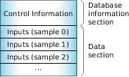 Figure 1. The shared memory layout.