 |
The two sections, “Writing an analog mixer” and “Using a standard mixer DLL,” are mutually exclusive; you need only one of them, depending on your card evaluation. |
|
The two sections, “Writing an analog mixer” and “Using a standard mixer DLL,” are mutually exclusive; you need only one of them, depending on your card evaluation. |
The easiest place to start in writing your Audio HW DLL is the analog mixer, because it's the simplest part of controlling a card; it doesn't involve any realtime constraints and small mistakes generally don't crash the machine. When you're using DMA, it's possible to overwrite the kernel, so we'll save PCM programming for later (see the Handling PCM Audio Data chapter).
In addition, if your card has an analog input (e.g. CD or Line In), it's very easy to test the analog mixer in isolation from the rest of the sound card. In contrast, without volume controls to adjust, it's very difficult to verify that your PCM playback (and capture) code is functioning correctly.
If your card uses one of the standard codecs (listed in the Supported Codecs appendix), see “Using a standard mixer DLL,” later in this chapter.
If you have a nonstandard or unsupported codec, you must define a set of mixer elements for it. A simplified codec has the following structure:
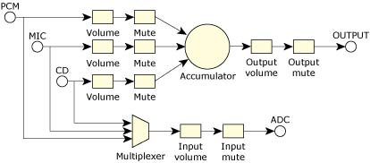
A simplified codec for an analog mixer.
In our terminology, all of the shapes are called mixer elements, and the lines are mixer routes. Some mixer elements are informational only.
The OUTPUT element is an I/O type element and holds only information such as the number of channels it contains. Other elements provide control by means of callback functions; for example, the volume elements have a callback that's used to read and set their associated gain level.
One common variation on this design is where all or some of the inputs can be mixed together into the ADC (Analog Digital Converter). This is usually done using a series of switches instead of the multiplexer.
The last important idea is that every element is routed to and from at least one other element. Only I/O elements break this rule.
The hardware design of the chip you're supporting dictates the elements and routes for the mixer. In fact, the diagram of your mixer might be similar to the example above, but is probably more complicated.
As an example, the standard AC97 diagram, has approximately 13 I/O elements and approximately 43 elements in total.
To translate the diagram to mixer software, you need to create a mixer element for every symbol on the diagram, and then create a route for every line.
At this point it's useful to discuss all the supported elements types, their respective attributes, any associated controls, and the function you can call to create one:
Creation function: ado_mixer_element_accu1()
Creation function: ado_mixer_element_accu2()
Creation function: ado_mixer_element_accu3()
Creation function: ado_mixer_element_io()
Creation function: ado_mixer_element_mux1()
Creation function: ado_mixer_element_mux2()
Creation function: ado_mixer_element_pcm1()
Creation function: ado_mixer_element_pcm2()
Creation function: ado_mixer_element_sw1()
Creation function: ado_mixer_element_sw2()
Creation function: ado_mixer_element_sw3()
Creation function: ado_mixer_element_volume1()
You can associate instance data with the more complex elements. If you need to access this instance data later, you have to call ado_mixer_get_element_instance_data() because ado_mixer_delement_t is an opaque data type.
In the simplest terms, a mixer group is a collection or group of elements and associated control capabilities. For the purpose of simplifying driver coding, we further define groups as relating to either playback or capture functionality:
Creation function: ado_mixer_playback_group_create()
Creation function: ado_mixer_capture_group_create()
The input selection element is either a multiplexer or an input switch. With these restrictions, the group control logic can be contained entirely within the io-audio module. To create a group, you can simply specify the group name, type, and its component elements.
Unlike elements and routes, mixer groups aren't strictly dictated by the hardware. You, as the driver writer, can decide on the number and contents of mixer groups. In order to build a useful driver, you need to create mixer groups with a logical design that attempts to satisfy the following conditions:
For example, the standard Photon mixer application displays and manipulates only mixer groups.
It's possible to make the PCM, MIC, and CD capture groups contain the input volume and input mute elements, but this would lead application developers to believe there are independent volume and mute controls on the these inputs, when clearly they're shared.
For the purposes of demonstration, we assume that the simplified codec shown in the previous figure represents the mixer that you plan to support. The rest of this chapter demonstrates how to translate this relatively standard diagram into code.
The complete code for the sample mixer in this chapter is available in the Sample Mixer Source appendix.
Before we can write any of the mixer code, we need to get some basic requirements of the driver out of the way. We need a build environment to build this code as a DLL, and we need to provide a standard entry point for io-audio to call to initialize the chip. The easiest way to do this is to copy the Sound Blaster driver directory ( sb ) to a directory named for your card.
After copying the directory, you should rename the C, header, and usage-message files to something more descriptive of your chip. After doing this, make sure the code still compiles before proceeding.
As described earlier, your Audio HW DLL must provide an entry point called ctrl_init(). The Organization of a Driver chapter describes the initialization that this function must do no matter what features your DLL supports.
If you're writing a custom audio mixer, the next task to perform (after ctrl_init() function has done the common part of the initialization) is to allocate and initialize a new ado_mixer_t structure.
Do this by calling ado_mixer_create(). All the information pertaining to this mixer is attached to this structure, so you need to store a copy of the returned pointer somewhere (usually in your context structure), so that you can access it later. However, ado_mixer_t is an opaque data type; your Audio HW DLL doesn't need to know what's in it.
Here's an example of initializing your Audio HW DLL if you're writing your own audio mixer:
int
example_mixer (ado_card_t * card, HW_CONTEXT_T * example)
{
  int32_t status;

  if ( (status = ado_mixer_create
       (card, "Example", &example->mixer, example)) != EOK )
    return (status);

  return (0);
}

ado_ctrl_dll_init_t ctrl_init;

int
ctrl_init( HW_CONTEXT_T ** hw_context, ado_card_t * card,
           char *args )
{
  example_t *example;
  if ((example = (example_t *) ado_calloc (1,
                                  sizeof (example_t))) == NULL)
  {
    ado_error ("Unable to allocate memory (%s)\n",
      strerror (errno));
    return -1;
  }

  *hw_context = example;

  /* Verify that the hardware is available here. */
  if (example_mixer(card, *hw_context) != 0)
    return -1;
  else
    return 0;
}
If you need to allocate memory for your mixer, you should create a cleanup function for io-audio to call when your mixer is destroyed. For more information, see ado_mixer_set_destroy_func().
You can also create a function to be called when the mixer's hardware is reset, but this usually isn't necessary. For more information, see ado_mixer_set_reset_func().
You must next construct a description of the mixer from its component parts. As mentioned earlier, a mixer consists of mixer elements, routes, and groups. In this example, there are 17 mixer elements, 18 routes, and 8 groups. The elements and routes are relatively straightforward to identify.
Elements are any of the symbols, and routes are the paths that data can travel between them. Use the functions listed above to create the elements; use ado_mixer_element_route_add() to create the routes.
|
Don't forget to count the point sources and point sinks as elements. Though they may not be drawn as solid symbols, they are important parts of the audio architecture. |
Identifying the groups is a little more troublesome. That's the reason why we enforce the rules on what can be in a group. It simplifies choosing how to divide the elements up into groups, and makes the drivers more consistent in form and behaviour. The eight groups are Master Output, Input Gain, PCM OUT, MIC OUT, CD OUT, PCM IN, MIC IN, and CD IN.
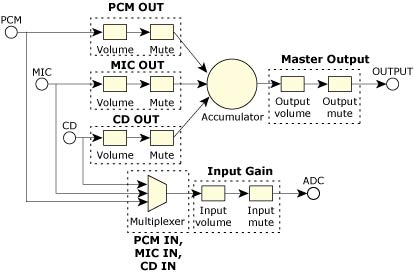
The groups in the sample analog mixer.
The PCM IN, MIC IN, and CD IN groups include the multiplexer, but specify a different input to it.
To build the mixer, first create the elements and routes, then pass pointers to the required elements to the functions that create the mixer group.
Here's the section of code that creates the master group, including all elements and routes:
int
build_example_mixer (MIXER_CONTEXT_T * example,
                     ado_mixer_t * mixer)
{
  int     error = 0;
  ado_mixer_delement_t *pre_elem, *elem = NULL;

  /* ################ */
  /* the OUTPUT GROUP */
  /* ################ */
  if ( (example->output_accu = ado_mixer_element_accu1
       (mixer, SND_MIXER_ELEMENT_OUTPUT_ACCU, 0)) == NULL )
    error++;

  pre_elem = example->output_accu;

  if ( !error && (elem = ado_mixer_element_volume1
       (mixer, "Output Volume", 2, output_range,
        example_master_vol_control,
        (void *) EXAMPLE_MASTER_LEFT, NULL)) == NULL)
    error++;

  if ( !error && ado_mixer_element_route_add
       (mixer, pre_elem, elem) != 0 )
    error++;

  example->master_vol = elem;
  pre_elem = elem;

  if ( !error && (elem = ado_mixer_element_sw2
       (mixer, "Output Mute", example_master_mute_control,
       (void *) EXAMPLE_MASTER_LEFT, NULL)) == NULL )
    error++;

  if ( !error && ado_mixer_element_route_add
       (mixer, pre_elem, elem) != 0 )
     error++;

  example->master_mute = elem;

  pre_elem = elem;

  if ( !error && (elem = ado_mixer_element_io
       (mixer, "Output", SND_MIXER_ETYPE_OUTPUT, 0, 2,
        stereo_voices)) == NULL )
    error++;

  if ( !error && ado_mixer_element_route_add
       (mixer, pre_elem, elem) != 0 )
    error++;

  if ( !error &&
       (example->master_grp = ado_mixer_playback_group_create
       (mixer, SND_MIXER_MASTER_OUT, SND_MIXER_CHN_MASK_STEREO,
       example->master_vol, example->master_mute)) == NULL )
    error++;

  return (0);
}
Don't feel that you must have all the mixer elements represented in the mixer groups. This isn't the point. The mixer elements and mixer groups are meant to be complementary. Nonstandard, complex, or just plain weird controls may not be needed at the mixer group level. They may be better as a simple mixer element or mixer switch. The mixer groups are intended to help the developer of audio applications figure out which mixer elements are related to each other and to a particular connection (e.g. PCM OUT).
In this sample mixer, none of the individual input groups (PCM IN, MIC IN, CD IN) has volume or mute controls. They're still required because they contain the capture selection switch, but the only volume and mute controls on the input side are in the Input Gain group. This is important to note because it points out that you don't need to completely fill the requirements to specify a group. If you're missing a mixer element in your hardware, you can specify NULL for the missing element, if it makes sense to group them that way.
If your card uses one of the standard codecs (listed in the Supported Codecs appendix), the amount of work you have to do is reduced.
The benefit of using standardized codecs is that you just have to write a few access functions, typically the ones that read and write the codec registers.
Before we can write these functions, we need to get some basic requirements of the driver out of the way. We need a build environment to build this code as a DLL and we need to provide a standard entry point for io-audio to call to initialize the chip.
The easiest way to do this is to copy one of the existing driver directories (/audio/src/hardware/deva/*) in the DDK to a directory named for your card or chip type. The best code to copy is either the template driver or the Sound Blaster (sb), depending on your answers to the questions in the Evaluating Your Card chapter. After copying the directory, you should rename the C, header, and use files to something more descriptive of your chip. After doing this, make sure the code still compiles before proceeding.
As described earlier, your Audio HW DLL must provide an entry point called ctrl_init(). The Organization of a Driver chapter describes the initialization that this function must do no matter what features your DLL supports.
After you've verified that the hardware exists, you need to map in the card memory if it's memory-mapped and initialize a mutex in the context structure. The mutex is used to make sure only one thread is accessing the hardware registers at a given point in time. Generally you lock the mutex around any routines that access card registers.
|
Keep the mutex locked for as little time as possible. |
Now that we have access to the hardware, the next step is to inform the upper layers of the driver of the capabilities of this hardware. We do this by creating devices: mixers and PCM channels. We'll look at creating the PCM device in the next chapter.
Since we have a standard codec, we use the ado_mixer_dll() function to create the mixer structure and load the appropriate mixer DLL. The prototype is:
int32_t ado_mixer_dll( ado_card_t *card,
                       char *mixer_dll,
                       uint32_t version,
                       void *params,
                       void *callbacks,
                       ado_mixer_t **rmixer );
The arguments to ado_mixer_dll() include:
The data types and contents of the params and callbacks structures depend on the mixer DLL that you're loading; see the Supported Codecs appendix for details.
The params structure is the key to making the mixer work correctly. It tells the mixer DLL about functions that you've written in your Audio HW DLL, typically to read and write the codec registers. This structure contains pointers to a hw_context structure and (typically) functions that read and write the codec registers. The hw_context is generally, but it doesn't need to be, the same context that you allocated at the beginning of the ctrl_init() function. The hw_context is passed back to you as a parameter when the mixer DLL calls the read or write routines.
|
Be sure to thoroughly test the callbacks that read and write the codec registers. If they don't work correctly, the mixer DLL might misbehave or fail. |
The callbacks structure tells you about functions that are defined in the mixer DLL that your Audio HW DLL needs to call in order to control the device. The ado_mixer_dll() function fills in this structure, based on the mixer DLL that you're opening.
To test this code, start up the driver and input an analog signal to one of the codec inputs (line, CD, etc.). Then, using the GUI mixer, try to control the volume of that signal at the speakers. Once this works reliably, you can move onto the next chapter.