There are different ways to connect a camera to your target board. Before you boot the reference image for your target platform, ensure you have the correct DIP switch settings on the Vision board based on the camera you have connected.
The following section shows the necessary DIP switch settings that you should set before you boot your target. For detailed information about the supported platforms, platform variants, and revisions, see the QNX Platform for ADAS Release Notes. In addition to modifying the DIP switch settings, you may need to change configuration files on the reference image. For more information about changing the configuration settings on the reference image, see “Configure cameras on the reference image”.
For information about connecting board power supplies, screens, and other peripheral devices, see the Board Support Package (BSP) User's Guide for your board on the QNX BSP and Drivers website.
Configure the hardware on the Jacinto 6 EVM
The reference image for the Jacinto 6 EVM board is configured to boot automatically. For more information about the various options available to configure the Jacinto 6 EVM board, see the BSP User's Guide for the Jacinto 6 EVM board for this QNX SDP 6.5.0 SP1.
- To use cameras connected with an FPD-Link III interface
- You can connect multiple cameras using FPD-Link III interfaces to a deserializer board. There are six interface ports on the board. The column of interface ports (inner part of the board) are numbered as 0,2,4, while the ports in the left column (closer to the edge of the serial board) are numbered 1,3,5. The deserializer board is connected to the Vision Board as shown in the following illustration:
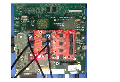
Figure 1. Deserializer board (red) connected to the Vision Board on the Jacinto 6 EVM board with FPD-Link III interface connectionsHere's what the cameras connected to the deserializer board using FPD-Link III interfaces look like: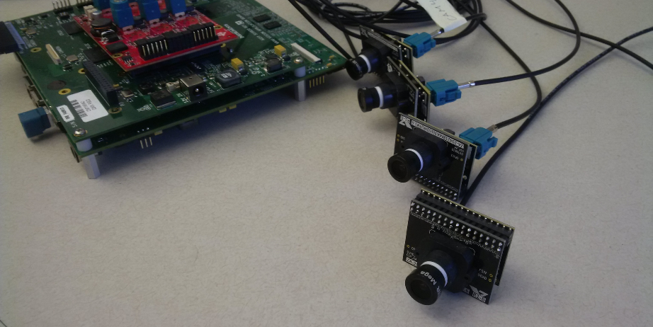
Figure 2. FPD-Link III interface cameras - For this configuration, ensure that the SW3 switch settings on the Vision Board are set to:
-
Off, Off, On, Off, Off, On, Off, On
- For more information about settings for the Jacinto 6 EVM board and Vision Board, see the Jacinto 6 EVM board BSP User's Guide.

Figure 3. SW3 DIP switch settings for cameras connected with an FPD-Link III interface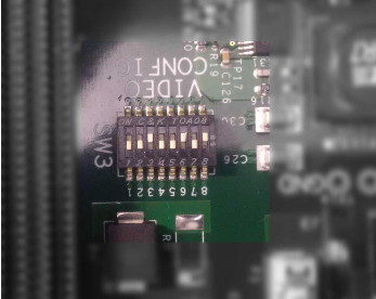
Figure 4. Vision Board SW3 settings for using cameras connected via an FPD-Link III interface - To use a camera connected with a parallel interface
- You can connect a camera directly to the Vision board using a parallel interface as shown in the following illustration:
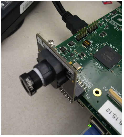
- For this configuration, ensure that the SW3 switch settings on the Vision board are set to:
-
Off, On, Off, On, Off, On, Off, On
- For more information about settings for the Jacinto 6 EVM board, see the BSP User's Guide.
 Figure 5. SW3 DIP switch settings for a camera connected with a parallel interface on the Vision BoardHere’s how your switches should look:
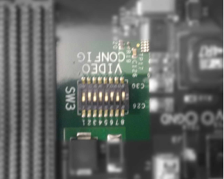
Figure 6. Vision Board SW3 settings for using cameras connected via a parallel interface
Boot the board
- Insert the microSD with the image into the target platform's microSD card slot. For more information, see Transfer an image to a target.
- Connect the target platform's power supply and power up the board. If you have four cameras connected with FPD-Link III interfaces, you should see four images in a 2x2 grid, similar to the following display:If you have a different configuration, such as one USB camera or even no cameras, you must change the configuration files used on the image. For more information about changing the required configuration files, see “Configure cameras on the reference image”.

Figure 7. Camera MUX 2x2 application runs when four cameras are connected by FPD-Link III interfaces