![[Previous]](prev.gif) |
![[Contents]](contents.gif) |
![[Index]](keyword_index.gif) |
![[Next]](next.gif) |
|
|
|
|
 |
This version of this document is no longer maintained. For the latest documentation, see http://www.qnx.com/developers/docs. |
Traditional power management (PM) is aimed at conserving the power of computers that are usually left on. The general-purpose approach to PM for desktop PCs -- or even for "mobile" PCs, such as laptops -- doesn't take into account the specific demands of embedded systems, which can be off (or on standby) much of the time, yet must respond to external events in predictable ways.
The two main industry standards for PM -- APM and its successor ACPI -- deal with PCs, not embedded systems. The older APM standard was BIOS-oriented (how many embedded systems even have a BIOS?). The newer ACPI is more OS-focused and therefore more sophisticated, but the standard expressly concerns itself with desktops, laptops, and servers. An OS can never anticipate the application-specific scenarios of embedded systems and make appropriate power policy decisions.
Given the sheer variety of embedded systems (e.g hand-held medical instruments, network routers, in-car telematics systems, to name but a few), the application developer is in the best position to know the specific power-related needs of the system in question.
The QNX PM framework is precisely that -- a framework or set of mechanisms that developers can use to control and manage power in their embedded systems. The OS doesn't impose a power policy. Instead, you create your own policy based on the specific needs of your application.
The PM framework consists of these main components:
| Framework component | Description |
|---|---|
| Power manager | A process that implements the system's PM policy. This policy is user-written -- the system designer creates a custom policy for the embedded system, and has full control over device power modes for the various operational modes of the system. |
| Power-managed objects | These represent hardware or software components that can be independently power-managed. Device drivers for power-managed devices interact with the power manager to control device power modes according to the system's PM policy. |
| Power-aware applications | These are user-written applications that interact with the power manager. They provide functionality specific to the embedded system (e.g. monitoring environmental conditions that could affect the desired operational mode of the system). |
| Persistent storage services | These allow device drivers to preserve hardware and software configuration details when the system is placed in a standby mode. The developer can customize the physical storage location of this persistent data for the embedded system. |
| BSP support | Code within the board-specific IPL and startup programs implements the board- and CPU-specific support for sleep/standby modes. |
These components are built using the following:
The QNX PM framework facilitates application-specific designs.
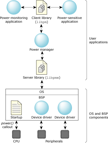
As the central component within the PM framework, the power manager is responsible for coordinating the power modes of each power-managed object according the system's PM policy.
The power manager is implemented as a user-written process that uses the libpmm library to manage the interactions with device drivers and power-aware applications.
The power manager consists of three main components:
The functionality for handling this communication is implemented entirely within the libpmm library.
The policy is customizable. Your policy is informed whenever an operation is performed on an object. This allows your policy code to track the state of an object, and where appropriate, to allow or deny certain operations. For example, your policy may deny requests to change the power mode of an object if the new mode isn't compatible with the system's current power-mode state.
The libpm library provides basic default behavior for these operations, so the system-specific policy needs to override only those operations that are required to implement the system's PM policy.
The most basic power manager simply initializes the resource manager interface to handle driver and client requests, and then starts a thread pool to service them:
#include <sys/procmgr.h>
#include <sys/pmm.h>

int
main()
{
    // initialize and start resource manager interface
    pmm_init(0, 0);
    pmm_start(0, 0);

    // become a daemon
    procmgr_daemon(0, 0);
    pthread_detach(pthread_self());
    pthread_exit(0);
    return 0;
}
This is sufficient to completely handle dynamic attachment by any drivers that start after the power manager; it implements a simple default policy that allows all power-mode changes to proceed as requested.
The libpmm library handles the low-level details of interacting with device drivers and power-aware applications. However, the decisions about what actions are allowed to proceed are policy decisions that developers customize for their embedded system.
The library invokes this policy code whenever requests arrive that affect a power-managed object's state. If you don't supply you own policy function, an internal default is used.
The policy is informed (by invoking policy callback functions) when:
An embedded system may pass through a number of different power states. Each state defines the functionality and allowed power modes for the various power-managed objects in the system.
For example, an automotive device may define the following system states:
| System state | Description |
|---|---|
| ACTIVE | A fully operational state where all devices may be powered up. Within this state, individual devices can be powered down when not being actively used, but are allowed to be powered up when required. |
| CRANK | A nonoperational state where the system is powered down during an engine crank. When the engine has started, the system returns to an active state. |
| SLEEP | A nonoperational state where devices are powered down and system RAM is held in self-refresh mode. This implements a "soft off" state that allows the system to become fully operational with short latency. Certain devices are configured to act as wakeup sources. For example, an RTC may be used to limit the time spent in this state. If the RTC timeout expires, the system will move to a lower power-standby state to further reduce power consumption. |
| STANDBY | A nonoperational state where devices are powered down and system RAM is disabled. This provides a lower-power "soft off" state, where the system can return to its previous operational state state with a slightly longer latency, since it requires a warm reboot. Certain devices are configured to act as wakeup sources. For example, activating a key lock or phone interface would return the system to an active state, or an RTC can be used to periodically wake the system to ensure the system shuts down completely when the battery level reaches a certain threshold. |
| OFF | The entire system is powered down to prevent its consuming any battery power. |
These system states can typically be modeled using a state machine, where system-specific events are used to cause transitions between states:
The policy callbacks interact with the state machine implementation to limit the allowed operations for the current system state, and to keep track of the status of each power-managed object so that they can be appropriately managed during state transitions.
Each entity that can be independently power-managed is represented by the power manager as a power-managed object.
The power manager's system PM policy determines the allowable power mode for each object, based on the system's current operational state. For example:
Power-managed objects are typically used to represent power-managed peripheral devices, allowing the power manager to control the device's power level. However, power-managed objects can also represent specialized applications. In this case, their operational characteristics are exposed to the power manager via its power mode; the power manager can control the application's behavior by changing its mode when the power manager changes the system's power-mode state.
The power manager presents all power-managed objects via a hierarchical namespace under /dev/pmm. This namespace provides a simple configuration database that can represent both physical and logical relationships between objects:
Device drivers for power-managed devices register with the power manager by attaching to a node within the namespace or by creating a new node in the appropriate location. Once attached, the driver is responsible for responding to requests from the power manager to manage the device's power mode.
The framework allows for both statically and dynamically configured systems:
How and when a driver is started makes no difference to the power manager; as soon as a driver registers with the power manager, its device will be managed according to the system's PM policy.
The framework defines four generic power modes that are universally applied to all power-managed objects. These primarily define the operational state of the object, and by implication, its power level:
| Power mode | Description |
|---|---|
| ACTIVE | A fully operational state where hardware is powered up. This is the normal operating mode. |
| IDLE | A partially operational state, where hardware can be
partially powered. From a user's point of view, the object
is fully operational; if necessary, it will become ACTIVE to
service user requests that can't be handled within the IDLE
power mode.
This mode is typically used only for dynamic power optimizations by a driver itself. For example, if it determines that its device isn't in use, it may enter an IDLE mode to conserve power. When the device is next used, it will move back to ACTIVE. |
| STANDBY | A nonoperational state, where hardware is powered down.
This mode is used by the power manager when the system as a
whole is being powered down to a low-power standby state.
Entering a STANDBY state typically requires a driver to save the context needed to reinitialize a device to an ACTIVE state (e.g. because the device hardware context or the system standby mode disables system RAM, requiring the driver to preserve the software state). |
| OFF | A nonoperational state, where hardware is powered off. Entering the OFF state doesn't require the driver to save any context. |
Note that all power-managed objects support the four operating modes, even if there's no specific IDLE or STANDBY mode.
If there's no IDLE mode, the object implements the IDLE mode using the same operational characteristics and hardware power level as its ACTIVE mode instead.
If there's no specific STANDBY, the object implements the STANDBY mode using the same physical power level as its OFF mode. In this case, the only difference is that entry into STANDBY may require the object to save context needed to reinitialize to an ACTIVE state.
These generic power modes provide a uniform way for the power manager (or power-aware applications) to control and reason about the power levels and functionality of a power-managed object, without requiring any device-specific knowledge.
The framework allows devices to implement an arbitrary number of additional device-specific modes that are sublevels of these four generic modes. For example, a driver may define:
These device-specific modes allow finer-grained control over a device's power mode and operational characteristics where appropriate.
Each power-managed object may have arbitrary properties associated with it. Each property consists of an identifier,value pair:
The power manager's policy code is told whenever a property value is changed. This allows the policy code to respond to changes that are relevant to evaluating the optimum system power state.
The framework allows user-defined properties to be associated with any object, so you can define arbitrary PM-related properties or attributes that can be manipulated by the power manager or power-aware applications. For example, you can have properties defined that describe battery power levels, vehicle bus status, or other environmental conditions relevant to the embedded system.
Power-aware applications communicate with the power manager using an API implemented by the libpm library. The API allows the application to manipulate power-managed objects by:
Power-aware applications fall into two main categories:
This information can be represented using power manager properties. The monitoring application can update the property value to inform the power manager's PM policy. The policy can then use this information to evaluate the appropriate system power state.
Power-sensitive applications can also request to change the power mode of an object, which can be used by the power manager's PM policy to intelligently decide which devices are eligible to be powered down at any given time.
Most CPUs support a low-power mode, where the CPU and peripherals are powered down with DRAM maintained in self-refresh mode. But for embedded systems that spend most of their time in a standby state for prolonged periods of time, this is unacceptable, because the power used for self-refresh over prolonged periods will exceed the reserve capacity provided by limited battery sources.
For these systems, the typical standby state will disable DRAM, so that only the limited hardware necessary to wake the system remains powered. When the system is woken up, a warm reboot is performed; the power manager then needs to reinitialize the system according to the power-mode state it decides the system should be in. This may require drivers or power-aware applications to save volatile configuration information in persistent storage so that this information can be recovered when they are restarted.
Services for persistent storage are provided by a persistent storage manager that controls one or more persistent stores. These persistent stores can make use of a number of different media:
| Media | Features |
|---|---|
| Shared memory | Can preserve data across application restarts. Note that this data isn't preserved across system reboots. |
| Raw flash partitions | Can be used when system RAM isn't preserved. This data can then be retrieved when the system is restarted. |
| Flash filesystem | As with a raw flash partitions, this data is preserved across system reboots. |
| Specialized memorya | Can be maintained for limited periods of time even if system RAM is disabled. Although these do require some power to maintain, the latency to save and restore persistent data is much lower than flash. This may be useful where the system must be powered down very quickly and will be powered back up within a reasonably short period of time (e.g. during an engine crank). |
| Custom storage | Can be implemented using an internal storage interface in the persistent storage manager. |
a For example, SRAM or a limited set of SDRAM banks that remain in self-refresh mode.
The persistent storage manager can manage multiple storage media, with one of those selected as the currently "active store." The underlying storage is hidden from clients, who simply request to save or restore their data.
Your power manager controls the choice of media used. Given your custom set of available stores for your embedded system, your power manager policy sets the "active store" based on the nature of the standby state it is entering before powering down the system.
Many CPUs offer a variety of available operating modes that provide different levels of power consumption:
The system as a whole is fully operational; these different modes simply provide a tradeoff between performance and power consumption.
The system as a whole is fully operational; this mode simply reduces the power consumption due to CPU activity. However, the device will still draw power for peripherals and RAM refresh.
This mode is generally used by the kernel's idle loop to reduce power consumption when there are no runnable threads, without impacting the system's realtime performance in responding to peripheral interrupts.
For some system-on-chip processors, this mode may also power down on-chip peripherals, further reducing the overall power consumption.
The latency to return to normal operation is relatively long because the memory controller and on-chip peripherals may need to be reinitialized. However, the system state remains preserved in RAM -- this can be a way to significantly reduce system power consumption while still providing a relatively low-latency to return to a fully active system.
Returning to normal operation is essentially a complete system reboot, because all system state information preserved in RAM is lost. However, this provides the lowest power consumption of all, requiring power for only those components required to wake up the CPU.
The power manager's PM policy determines which CPU modes are appropriate for the various system states required for your device. Remember that this policy is user-written -- as the embedded system designer, you are in the best position to decide on the optimum balance between power consumption and performance or latency to return to an operational mode.
These CPU modes are highly processor-specific. Also, the nature of the wakeup sources depends on the system hardware implementation. For this reason, the implementation is provided by the power() callout within the BSP-specific startup program, and may also require support from the BSP-specific IPL (if the CPU wakeup causes a warm reboot via the reset vector).
Reference implementations provide the basic CPU-level support required for the modes supported by a particular CPU. You may then customize this as required to handle board-specific wakeup configuration, if necessary.
|
|
|
|