If you have a nonstandard or unsupported codec, you must define a set of mixer elements for it. A simplified codec has the following structure:
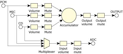 Figure 1. A simplified codec for an analog mixer.
In our terminology, all of the shapes are called mixer elements, and the lines are mixer routes. Some mixer elements are informational only.
The OUTPUT element is an I/O type element and holds only information such as the number of channels it contains. Other elements provide control by means of callback functions; for example, the volume elements have a callback that's used to read and set their associated gain level.
One common variation on this design is where all or some of the inputs can be mixed together into the ADC (Analog Digital Converter). This is usually done using a series of switches instead of the multiplexer.
The last important idea is that every element is routed to and from at least one other element. Only I/O elements break this rule.
The hardware design of the chip you're supporting dictates the elements and routes for the mixer. In fact, the diagram of your mixer might be similar to the example above, but is probably more complicated.
As an example, the standard AC97 diagram, has approximately 13 I/O elements and approximately 43 elements in total.
To translate the diagram to mixer software, you need to create a mixer element for every symbol on the diagram, and then create a route for every line.