The main() function is typically short; it does the option processing and then calls the resource manager mainline. However, there's one important call in main() that should be pointed out:
ThreadCtl (_NTO_TCTL_IO, 0);
This function allows a root-owned process (or one that's setuid() to root) to access the hardware I/O ports. If you don't call this function, and attempt to do I/O port manipulation (via in8() for example), your process dies with a SIGSEGV.
Option processing is fairly standard as well, except that at the end of option processing we read in the configuration file. The configuration file drives the card installation (I've deleted some of the long error messages for clarity and brevity):
parser_t        *p;
parser_handle_t *ph;

...

if (ph = parser_open (optc)) {
  if (p = parser_parse (ph, "/dev/pcl711*")) {
   if (p -> status != PARSER_OK) {
      // error message
      exit (EXIT_FAILURE);
    }
    if (optv) {
      parser_dump (p);
    }
    install_cards_from_database (p);
    parser_free (p);
  }
  parser_close (ph);
} else {
  if (optc) {
    // error message
    exit (EXIT_FAILURE);
  } else {
    // warning message
  }
}
Basically, the logic is that we call parser_open() to get a parse handle, which we then pass to parser_parse(). Notice that parser_parse() is given a wild-card pattern of /dev/pcl711* to match—this is how we filter out only our card's information from the configuration file. This aspect of the driver names was one of the reasons that I create multiple mount points per driver, rather than just one. Finally, the real work is done in install_cards_from_database() (in pcl711.c).
Skipping vast amounts of code (the parser_*() functions—see the source code) and hiding the details, install_cards_from_database() boils down to:
int
install_cards_from_database (parser_t *data)
{
  int s;

  s = strlen ("/dev/pcl711-");

  for (nd = 0; nd < data -> ndevices; nd++) {
    card = install_card (d -> devname,
             strtol (d -> devname + s, NULL, 16));
    for (nc = 0; nc < d -> nchannels; nc++) {
      for (np = 0; np < c -> nports; np++) {
        for (naio = 0; naio < p -> naios; naio++) {
          // verify and optionally default configuration
        }
        for (ndio = 0; ndio < p -> ndios; ndio++) {
          // verify and optionally default configuration
        }
      }
    }
  }
}
We process all devices in the database (the first for loop). This is to handle the case where there are multiple PCL-711 cards installed; this iterates through all of them. The next for loop processes all of the channels on each card, and then the next for loop processes all of the ports on each channel. Finally, the two innermost for loops process the analog and digital points.
Notice that we call install_card() within the first for loop. This function registers the card name with the process manager via resmgr_attach().
Processing mainly involves range checking. For the PCL-711, the channels are organized like this:
| Channel(s) | Meaning |
|---|---|
| 0–7 | Analog Inputs |
| 8 | Analog Output |
| 9 | Digital Input (16 bits) |
| 10 | Digital Output (16 bits) |
There is no concept of a “port” on the PCL-711 card (nor on the ISO-813 card, for that matter), so we don't do any checking for ports in that logic.
An easy way to remember the ordering is with the name of the server, ADIOS. Analog channels are grouped together first, followed by digital channels. Within each group, the inputs are first, followed by the outputs.
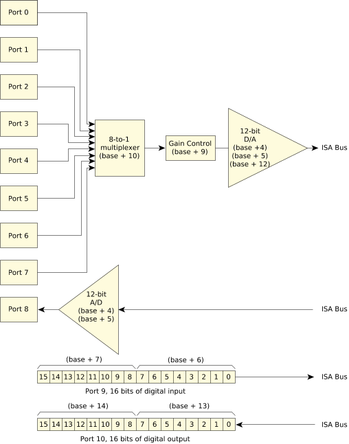 Figure 1. The PCL-711 card, with register offsets.
For reference, here are the channel assignments for the other two cards (DIO-144 and ISO-813), starting with the DIO-144:
| Channel(s) | Port(s) | Meaning |
|---|---|---|
| 0–5 | A, B, or C | Digital I/O |
On the DIO-144, ports A and B can be configured as input or output for the entire 8-bit port, whereas port C can be configured on a nybble (4-bit) basis (the upper or lower 4 bits have the same direction within each nybble, but the nybbles are configured independently). To obtain the base address for any given channel and port, multiply the channel number by 4 and add it to the base address plus the port offset.
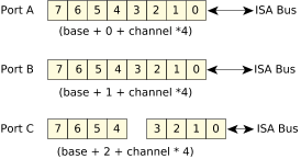 Figure 2. The DIO-144 card with register offsets.
On the ISO-813, the assignments are as follows:
| Channel(s) | Meaning |
|---|---|
| 0–31 | Analog input |
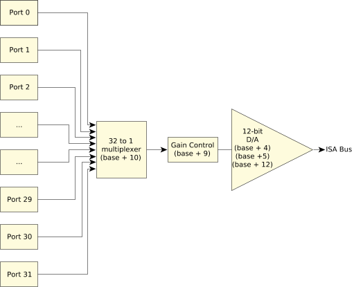 Figure 3. The ISO-813 card high-level view with register offsets.
When install_cards_from_database() returns, we have already registered the pathnames with the process manager (via install_card()) and configured it (again via install_card()). All that's left to do is to enter the resource manager main loop, execute_resmgr().
There's nothing special or different in execute_resmgr() that we haven't seen before in the other examples (like the web counter presented in the Web Counter Resource Manager chapter) so we won't discuss it.
What I will quickly discuss is the extended attributes structure:
typedef struct pcl711_s
{
    iofunc_attr_t   attr;
    int             port;
    char            *name;
    int             dout;
    int             gains [NAI];
}   pcl711_t;
As usual, the normal attributes structure is the first member of the extended attributes structure. Here are the other members:
- port
- I/O port that this device is based at.
- name
- ASCII name of the device (e.g. the string “/dev/pcl711-0200”).
- dout
- Shadow copy of the digital output for this card—see “Digital output,” below.
- gains
- This array stores the gain values (in card-native format) for each channel.
We'll see how most of these fields are used when we discuss the code for the analog and digital I/O functions.