Century Aluminum has several production lines where they smelt aluminum. Each line has several analog and digital I/O points that they monitor so they can feed data into the proprietary process control software that controls the line.
I was involved on the low-level driver and data acquisition side, and have no idea what they do with the data once it leaves the QNX Neutrino box.
The requirements for this contract came in two sets. The first set of requirements was to support three different hardware cards. For those of you not familiar with the industrial automation/process control world, the next statement will come as a surprise. The buses on all three cards are ISA (not PCI). These folks use rack-mounted PC's (with modern Pentium 3-class CPUs), with a huge ISA bus—some of them have room for up to twenty ISA cards! The three cards are the DIO-144 (144 digital I/O pins), PCL-711 (16 digital I/O, 8 analog inputs, and 1 analog output), and the ISO-813 (32 analog inputs).
The second set of requirements was for something to periodically read the data from the cards, and put that data into shared memory. The idea was that Century Aluminum's control software would then grab samples out of shared memory, do the processing, and control the lines.
As with all software projects, there were some extras that got included into the contract just because they came in handy during development. One of these extras was a showsamp utility that displayed samples out of the shared memory maintained by ADIOS. Another one was called tag and it lets you query or set various analog or digital I/O channels. Finally, a master parser was created to handle the configuration file. This was incorporated into the drivers, ADIOS, and tag, so everything could be referred to by a symbolic name (like OVEN_CONTROL_1, rather than “card at address 0x220, channel 3, port B, bit 4”). For analog ports, the configuration file also contained range information (so that a 12-bit analog converter might actually be scaled to represent voltages from -5V to +5V, rather than a raw binary value from 0x000 to 0xFFF).
So, in this chapter, we'll look at the following pieces of software:
- Card drivers: pcl711, dio144, and iso813
- ADIOS server: adios
- Show sample utility: showsamp
- Tag utility: tag
We'll also discuss some of the common code that's shared between modules.
This high-level diagram shows the pieces that we'll be discussing:
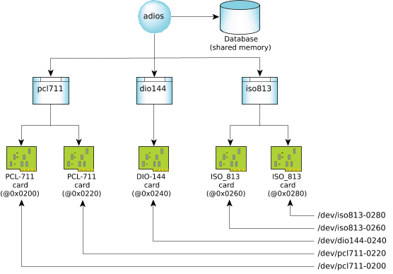 Figure 1. The relationship between ADIOS, the shared memory database, the hardware drivers, and their cards.