 |
This part of Foundry27 is now deprecated and is no longer being developed. |
This chapter describes how to write a graphics driver:
Before looking at the data structures and functions, it's important to understand the “big picture” for the Neutrino Graphics Driver Development Kit.
The purpose of the Graphics DDK is to allow third parties to write accelerated drivers without requiring QNX Software Systems to become involved in doing the work. It also allows you to customize graphics drivers supplied in source form.
This section includes:
You can download the source code for the graphics drivers from the Graphics project on our Foundry27 community website, http://community.qnx.com/sf/projects/graphics. For more information, see the “Quick Guide to the Graphics Source” section. You'll find the source code for the drivers under trunk/hardware/devg in the repository.
|
This part of Foundry27 is now deprecated and is no longer being developed. |
The Graphics repository on Foundry27 includes sample drivers for the following:
Note that the driver framework includes a library called the FFB (Flat Frame Buffer). This library serves these main purposes:
For every 2D rendering entry point in a graphics driver, there's an equivalent software version in the FFB that takes identical parameters. Thus your driver isn't required to provide any rendering functions. When the graphics framework asks your driver to supply its 2D drawing functions, the driver can return a mixture of its own accelerated functions and software-implemented FFB functions.
For more information, see “FFB library — 2D software fallback routines” in the Libraries chapter.
Graphics drivers are implemented in a modular fashion. Graphics driver functionality is broken down into various groups. A graphics driver's shared object may supply one or more groups of functionality. The shared object contains one module per functional group that it implements.
A graphics driver exposes its functionality by supplying a well-known entry point per module.
The modules currently defined are:
Future modules can be implemented by defining a new well known entry point.
Enumeration is the process of discovering what kind of display hardware you have, what its capabilities are. A video mode defines a set of timing and other parameters that will drive a display device at a given resolution and refresh rate. Modeswitching is the process of putting the video card into one of its supported modes.
At the driver level, enumeration of the video modes supported by the hardware roughly corresponds to the VESA BIOS model. The driver returns a list of numbers corresponding to the modes the hardware supports, and then a driver function is called for each of the mode numbers, returning information about that mode.
Switching to a given mode is accomplished by calling a driver entry point with one of the supported mode numbers.
2D drawing routines are the functions that actually produce or manipulate a two-dimensional image.
Operations that fall into this category include:
BLIT routines include operations that render an image that's in system RAM into the framebuffer and routines that move a rectangular portion of the screen from one place to another.
Offscreen memory management routines are used to manage multiple 2D objects, or surfaces, which the graphics driver may draw into (whether the surfaces are on the visible display, or not).
Most modern video cards have far more memory than is actually needed for the display. Most of them also allow the graphics hardware to draw into this unused memory, and then copy the offscreen object onto the visible screen, and vice-versa.
Many embedded graphics chipsets don't have dedicated memory; these chipsets use system memory for graphics buffers. A driver may choose to reserve a section of memory and provide the memory functions to create a memory pool and to allocate and free surfaces. Alternatively, a driver can have these functions return NULL and let the graphics framework allocate the surfaces.
The memory management module deals with managing this memory. The routines in this module deal with allocating and deallocating 2D surfaces.
Some display controllers allow you to transparently overlay multiple “screens” on a single display. Each overlaid region is called a layer. Layers can be used to combine independent display elements. Because overlaying is performed by the display controller, this can be more efficient than rendering all of the display elements onto a single memory surface. For example, a fast navigational display can be implemented with the scrolling navigational map on a background layer and pop-up GUI elements, such as menus or a web browser, on the foreground layer. The foreground elements don't need to be redrawn every time the map is updated.
Layer capabilities vary, depending on the display controller and the driver. Some display controllers don't support layers. Different layers on the same display may have different capabilities. Layers are indexed per display, starting from 0, from back to front in the default overlay order. Some hardware supports dynamic re-ordering of layers.
The image to be displayed on a layer is fetched from one or more video memory surfaces. The layer format determines the number of surfaces needed by a layer. For example, a layer whose format is DISP_LAYER_FORMAT_ARGB8888 requires one surface, while a layer whose format is DISP_LAYER_FORMAT_YUV420 (planar YUV) requires three surfaces for a complete image.
The source viewport defines a rectangular window into the surface data. This window is used to extract a portion of the surface data for display by the layer. The destination viewport defines a rectangular window on the display. This window defines where the layer displays its image. Scrolling and scaling (if supported by the layer) can be implemented by adjusting these viewports.
You must include the file <display.h>, which contains structures that you use to bind your driver to the graphics framework. (“Graphics framework” here refers to the framework that underlies both Photon and libgf graphics libraries).
The graphics framework binds your graphics driver by calling dlopen() to load your driver, and then finding your primary entry point(s). Certain primary entry points are optional, depending on what functionality your driver supports. The following table lists the defined primary entry points:
| Functional block | Name of function |
|---|---|
| Core 2D drawing functions | devg_get_corefuncs() |
| Context 2D drawing functions | devg_get_contextfuncs() |
| Miscellaneous rendering functions | devg_get_miscfuncs() |
| Display control | devg_get_modefuncs() |
| Memory manager | devg_get_memfuncs() |
| Video capture | devg_get_vcapfuncs() |
The purpose of each primary entry point is to populate tables with the remainder of the drivers entry points. Note that the primary entry points can be called at any time, and are usually called before the graphics framework is fully initialized. For this reason, the primary entry points should only reference the following entries in the disp_adapter_t:
Since these members will be valid, it is possible to supply different driver entry point to the graphics framework, based on which version of the hardware is present.
All the primary entry points have a similar structure: the graphics framework passes to each a pointer to a disp_adapter_t structure, a pointer to a set of functions (the type of which depends on the function being called), and a table size in tabsize (plus other arguments as appropriate).
The disp_adapter_t structure is the main “glue” that the graphics framework uses to hold everything together. It tracks all of the states information pertaining to an instance of a display controller device.
Finally, the table size (tabsize) parameter indicates the size of the structure, in bytes. This is so that your initialization function doesn't overwrite the area provided. You should use the DISP_ADD_FUNC() macro (defined in <graphics/display.h>) to add function pointers to the tables; it automatically checks the tabsize parameter.
The idea is that newer drivers that supply more functions will run properly with older versions of the graphics framework that supply smaller function tables.
For more information, see the Graphics Driver API chapter.
Some driver entry points are called only from within io-display's address space:
Other entry points are called only from within the address space of the client:
The graphics framework calls your driver's functions as follows:
modeswitch->init ();
    modeswitch->set_mode ();
    mem->init ();
        misc->init ();
            ...
            // external clients attach
            misc->attach_external ();
            // at this point clients may call the driver's rendering functions
            ...
            // clients detach; the framework shuts everything down
        misc->fini ();
    mem->fini ();


    modeswitch->set_mode ();
    mem->init ();
        misc->init ();
        misc->attach_external ();
            ...
            // at this point clients may call the driver's rendering functions
            ...
            // shutdown of graphics drivers requested here
        misc->fini ();
    mem->fini ();
    // at this point no more graphics functions will be called
modeswitch->fini ();
Before looking at the function descriptions, there are some conventions that you should be aware of.
This section includes:
RGB colors that are passed to 2D drawing functions are in the same pixel format as the surface that's the target of the rendering operation.
However, chroma-key colors are passed with the 24-bit true-color value stored in the least significant three bytes. However, if the target of the draw operation is a palette-based surface, the palette index that corresponds to the color-key value is stored in the least significant byte.
With the exception of 3D entry points, the coordinate (0, 0) is the top left of the displayed area. Coordinates extend to the bottom right of the displayed area. For example, if your graphics card has a resolution of 1280 (horizontal) by 1024 (vertical), the coordinates are (0, 0) for the top left corner, through to (1279, 1023), for the bottom right.
The graphics framework passes only sorted coordinates to your driver. For example, if a draw-span function is called to draw a horizontal line from (x1, y) to (x2, y), the graphics framework always passes the coordinates such that x1 ≤ x2; it never passes them such that x1 > x2.
All coordinates given are inclusive, meaning, for example, that a call to draw a line from (5, 12) to (7, 12) shall produce three pixels (that is, (5, 12), (6, 12), and (7, 12)) in the image, and not two.
|
The coordinate order and inclusiveness rules described above don't apply to 3D coordinates, which are described later. |
Core 2D drawing functions are typically expected to perform very simple operations. With the exception of transformation, clipping, and pattern information, and information regarding the surface that's being drawn to, the core functions can ignore most of the information in the draw context structure.
Context 2D drawing functions are expected to be able to handle more complex operations, such as chroma-keying, alpha-blending, and complex raster operations.
Core functions may be coded to handle a single pixel format. However, context functions must be prepared to handle drawing to any of the possible 2D-targetable surface types.
Another difference is that the context functions are allowed to make calls to core drawing functions, but not the other way around. The draw state structure contains a pointer to the function table that contains pointers to the core functions, which allows the context functions access to the core functions.
Since context functions can be expected to perform complex operations, it often makes sense to perform the operation in multiple stages. Future optimizations in the FFB may entail having the FFB versions of the context functions making more calls to the core functions.
The graphics framework passes to every function, as its first argument, a pointer to a disp_draw_context_t structure that gives the function access to the draw state context block.
|
If your functions modify any of the context blocks during their operation,
they must restore them before they return.
If the graphics framework modifies the context blocks between calls to the draw functions, it then calls the appropriate update_*() function to inform you which parts of the context data have been modified. The graphics framework doesn't modify the context blocks while your function is running. |
When a 2D draw function (i.e. a function that's been supplied by the driver in either the disp_draw_corefuncs_t or the disp_draw_contextfuncs_t structure) is called, it's usually expected to perform the draw operation correctly before returning (i.e. it may not fail). The only exceptions to this rule are the filled polygon and polyline rasterization entry points.
The FFB (Flat Frame Buffer) library serves as a reference as to how 2D primitives are to be rendered. The draw functions that your driver supplies in its devg_get_corefuncs() and devg_get_contextfuncs() entry points are expected to produce the same rendering results as the FFB.
With typical graphics hardware, not all primitives can be rendered using hardware, while producing the same resulting pixels in the targeted draw surface as the FFB does. In order to perform the draw operation correctly, it's often necessary to call the FFB library functions to carry out a draw operation. This is called falling back on software.
Falling back on software can be achieved in these ways:
This has pleasant implications for the driver writer: it means that none of the 2D draw functions are mandatory, that is, the driver implementer can simply supply only FFB functions. Obviously this would lead to a far-from-optimal driver, since none of the draw functions would be taking advantage any hardware acceleration features.
Or:
Typically, the devg_get_corefuncs() and devg_get_contextfuncs() routines function as follows:
Using the above method makes your driver forward-compatible with future versions of the driver framework. If more draw functions are added to the specification, the graphics framework will pass in a larger structure, and an updated FFB library will fill in software versions of the new functions. The graphics driver doesn't need to be rebuilt or reshipped. At your discretion, you can update the graphics driver to supply accelerated versions of the new functions.
When a driver function is called to perform a draw operation, it typically checks members of the draw context structure, in order to determine if it needs to fall back on software. However, note that anytime the framework changes the draw context structure, it notifies the driver by means of one of the update-notification entry points.
As an optimization, your driver can perform these checks in its update() function (e.g. the disp_draw_contextfuncs_t's update_rop3() function) and set flags to itself (in its private context structure) that indicate whether or not it can render various graphics primitives without falling back on software. This saves each and every context function from having to perform this work at runtime; it just checks the flags in a single test.
Sometimes it is desirable to render to a memory surface which can't be targeted by the hardware. For example, if a graphics device has limited memory that can be accessed by the draw engine, and this memory runs out, the graphics framework may allocate regular system RAM instead, and render to the surface in RAM using software-only functions.
Instead of calling into the driver to render to this memory and having the driver check whether the currently targeted surface was hardware-renderable or not, the driver must supply software-only rendering functions to the graphics framework instead. The get_corefuncs_sw and get_contextfuncs_sw entry points will be called by the framework to populate tables with software-only functions. The driver will typically just populate these two entry points with ffb_get_corefuncs() and ffb_get_contextfuncs(), respectively.
In most cases, clipping is performed by the graphics framework before calling into the driver to render a primitive. However, some 2D entry points are required to clip the primitive to within the bounds of the rectangle defined by the following members of the draw context structure: clip_left, clip_top, clip_right, clip_bottom.
The coordinates (clip_left, clip_top) and (clip_right, clip_bottom) specify the upper left, and lower right corners of the clipping rectangle. Note that these clipping boundaries are inclusive.
The “core” entry points which are required to perform clipping are:
The “context” entry points which are required to perform clipping are:
Patterns are stored as a monochrome 8×8 array. Since many of the driver routines work with patterns, they're passed in 8-bit chunks (an unsigned char), with each bit representing one pixel. The most significant bit (MSB) represents the leftmost pixel, through to the least significant bit (LSB) representing the rightmost pixel. If a bit is on (1), the pixel is considered active, whereas if the bit is off (0), the pixel is considered inactive. The specific definitions of active and inactive, however, depend on the context where the pattern is used.
As an example, the binary pattern 11000001 (hex 0xC1) indicates three active pixels: the leftmost, the second leftmost, and the rightmost.
Note that functions that have 8x1 in their function names deal with a single byte of pattern data (one horizontal line), whereas functions that have 8x8 in their function names deal with an 8 by 8 array (eight horizontal lines).
The pattern is circular, meaning that if additional bits are required of the pattern past the end of the pattern definition (for that line) the beginning of the pattern (for that line) is reused. For example, if the pattern is 11110000 and 15 bits of pattern are required, then the first eight bits come from the pattern (i.e. 11110000) and the next 7 bits once again come from the beginning of the pattern (i.e. 1111000) for a total pattern of 111100001111000. See “Pattern rotation,” below for more details about the initial offset into the pattern buffer.
A similar discussion applies to the vertical direction: if an 8-byte pattern is used and more pattern definitions are required past the bottom of the pattern buffer, the pattern starts again at the top.
The driver must take care to ensure that when rendering, the correct bits of the pattern are applied to each pixel that is rendered. The X offset (and Y offset for 8×8 patterns) into the pattern which corresponds to a given pixel being rendered, can be calculated as follows:
    X offset <= (ctx->pat_xoff + dx) & 0x7;
    Y offset <= (ctx->pat_yoff + dy) & 0x7;
The ctx is the pointer to a structure of type disp_draw_context_t (which is passed into each draw function), dx is the X offset into the currently targetted surface of the pixel being rendered, and dy is the Y offset of the pixel being rendered.
A similar mechanism is used when applying an alpha map. In the case of an alpha map, the map can have an arbitrary width and height. The X and Y map offsets can be calculated as follows:
    X offset <= (ctx->alpha_map_xoff + dx) % ctx->alpha_map_width;
    Y offset <= (ctx->alpha_map_yoff + dy) % ctx->alpha_map_width;
The ctx is the pointer to a structure of type disp_draw_context_t dx is the X offset into the currently targetted surface of the pixel being rendered, and dy is the Y offset of the pixel being rendered.
The pixel formats are defined below.
|
You aren't expected to be able to render into the formats tagged with an asterisk (*). Therefore, these formats are never specified as parameters to devg_get_corefuncs(). |
In any case, if you receive a pixel_format that you don't know what to do with (or don't want to handle yourself), simply call ffb_get_corefuncs() to populate the function table with software rendering routines.
For RGB formats, the name indicates the layout of the color components. For example, for DISP_SURFACE_FORMAT_ARGB1555, the Alpha bit is stored in the most significant bit of the pixel, and the Blue component is stored in the least significant 5 bits.
You can use the DISP_BITS_PER_PIXEL() and DISP_BYTES_PER_PIXEL() macros in <graphics/display.h> to determine the number of bits or bytes of a packed surface format, including packed RGB and packed YUV format.
|
These macros don't work for planar formats. Before using them, you should examine their definitions in <graphics/display.h> to see exactly what they do! |
The layout of pixel data in memory is identical for big and little-endian hosts and graphics devices.
There is a per-surface flag, DISP_SURFACE_BYTES_REVERSED, that specifies whether the bytes within the surface are swapped. If this flag is not set, then data formats which are considered to be packed, are stored in little-endian order. The “reversed” flag currently only has meaning for 16 and 32 bit-per-pixel formats.
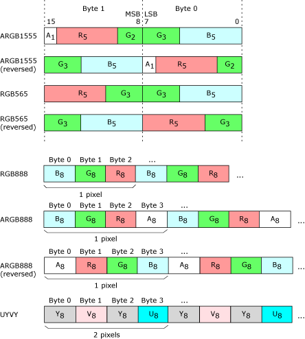
Byte order illustrated.
The pixel formats for layers are defined below.