![[Previous]](prev.gif) |
![[Contents]](contents.gif) |
![[Index]](keyword_index.gif) |
![[Next]](next.gif) |
|
|
|
|
 |
This version of this document is no longer maintained. For the latest documentation, see http://www.qnx.com/developers/docs. |
In this section, we'll examine the IPL program in detail, including how to customize it for your particular hardware, if you need to.
The initial task of the IPL is to minimally configure the hardware to create an environment that allows the startup program (e.g. startup-bios, startup-ixdp425, etc.), and consequently the Neutrino microkernel, to run. This includes at least the following:
The IPL's initialization part is written entirely in assembly language (because it executes from ROM with no memory controller). After initializing the hardware, the IPL then calls the main() function to initiate the C-language environment.
Once the C environment is set up, the IPL can perform different tasks, depending on whether the OS is booting from a linearly mapped device or a bank-switched device:
Note that we use the term "ROM" generically to mean any nonvolatile memory device used to store the image (Flash, RAM, ROM, EPROM, flash, battery-backed SRAM, etc.).
For linearly mapped images, we have the following sources:
For bank-switched images, we have the following sources:
In conjunction with the above, we have the following processors and configurations:
Let's assume we're booting from a bank-switched or paged device (e.g. paged flash, disk device, network, etc.), and that the image is uncompressed. The IPL needs to handle these main tasks:
Once the controller is set up, the function's task is to copy the image via the serial controller to a location in RAM.
unsigned long image_scan (unsigned long start, unsigned long end)
The image_scan() function:
int image_setup (unsigned long address)
The image_setup() function:
At this phase, the startup program has been copied to RAM (and it must always execute from RAM), and the startup header has been patched with the address of the OS image.
 |
Since the startup program is responsible for copying the
image filesystem to its final destination in RAM, the IPL
must copy the image to a location that's linearly
accessible by the startup program, which has no
knowledge of paged devices (serial, disk, parallel, network,
etc.).
Note also that if the image is compressed, then the IPL can copy the compressed image to a location that won't interfere with startup's decompression of the image to its final destination in RAM. When the image lives in flash (or ROM or whatever linear storage device), this isn't an issue. But when the image is stored on a paged device, more care must be taken in placing the image in a RAM location that won't interfere with startup's decompression of the image. Here are the rules:
|
int image_start (unsigned long address)
The image_start() function should never return; it returns -1 if it fails.
The function jumps to the startup_vaddr address as defined in the startup header.
For a system that boots from a linearly mapped device (e.g. linear flash, ROM, etc.), the IPL's tasks are the same as in the paged-device scenario above, but with one notable exception: the IPL doesn't need to concern itself with copying a full OS image from the device to RAM.
Your IPL code may be quite simple or fairly elaborate, depending on how your embedded system is configured. We'll use the terms warm start and cold start to describe the different types of IPL:
In this case, the IPL doesn't get control immediately after the reset, but instead gets control from the BIOS or ROM monitor.
The x86 PC BIOS allows extensions, as do various ROM monitors. During the power-up memory scan, the BIOS or ROM monitor attempts to detect extensions in the address space. To be recognized as an extension, the extension ROM must have a well-defined extension signature (e.g. for a PC BIOS, this is the sequence 0x55 and then 0xAA as the first two bytes of the extension ROM). The extension ROM must be prepared to receive control at the extension entry offset (e.g. for a PC BIOS, this is an offset of 0x0003 into the extension ROM).
Note that this method is used by the various PC BOOTP ROMs available. The ROM presents itself as an extension, and then, when control is transferred to it, gets an image from the network and loads it into RAM.
One of the benefits of Neutrino, especially in a cost-reduced embedded system, is that you don't require a BIOS or ROM monitor program. This discussion is primarily for developers who must write their own IPL program or who (for whatever reason) don't wish to use the default IPL supplied by their BIOS/monitor.
Let's take a look at what the IPL does in this case.
When power is first applied to the processor (or whenever the processor is reset), some of its registers are set to a known state, and it begins executing from a known memory location (i.e. the reset vector).
Your IPL software must be located at the reset vector and must be able to:
For example, on an x86 system, the reset vector is located at address 0xFFFFFFF0. The device that contains the IPL must be installed within that address range. In a typical x86 PC BIOS, the reset vector code contains a JMP instruction that then branches to the code that performs diagnostics, setup, and IPL functionality.
Regardless of the processor being used, once the IPL code is started, it has to load the image in a manner that meets the requirements of the Neutrino microkernel as described above. The IPL code may also have to support a backup way of loading the image (e.g. an .altboot in the case of a hard/floppy boot). This may also have to be an automatic fallback in the case of a corrupted image.
Note, however, that the amount of work your IPL code has to do really depends on the location of the image; there may be only a small amount of work for the IPL or there may be a lot.
Let's look again at the two classifications of image sources.
This is the simplest scenario. In this case, the entire image is stored in some form of directly addressable storage -- either a ROM device or a form of PC-Card device that maps its entire address space into the processor's address space. All that's required is to copy the startup code into RAM. This is ideal for small or deeply embedded systems.
Note that on x86 architectures, the device isn't required to be addressable within the first megabyte of memory. The startup program also needn't be in the first megabyte of RAM.
Note also that for PC-Card devices, some form of setup may be required before the entire PC-Card device's address space will appear in the address space of the processor. It's up to your IPL code to perform this setup operation. (We provide library routines for several standard PC-Card interface chips.)
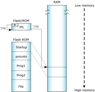
Linearly mapped device.
In this scenario, the image is stored in a device that isn't directly mapped into linear memory. An additional factor needs to be considered here -- how will your IPL code get at the image stored in the device?
Many types of hardware devices conform to this model:
Let's look at the common characteristics. In such systems, the IPL code knows how to fetch data from some piece of hardware. The process is as follows:
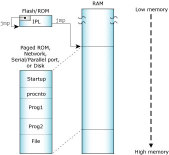
Bank-switched devices.
In this scenario, a solid-state storage device (ROM, EPROM, flash, etc.) contains the image, but the processor can see only a small portion of the contents of the device. How is this implemented? The hardware has a small window (say 32 KB) into the address space of the processor; additional hardware registers control which portion of the device is manifested into that window.
Large storage medium, bank-switched into a window.
In order to load the image, your IPL code must know how to control the hardware that maps the window. Your IPL code then needs to copy the image out of the window into RAM and transfer control.
|
If possible, avoid the use of any mapping hardware (whether custom-designed or "industry-standard") -- it only serves to complicate the hardware and software designs. We strongly recommend linearly mapped devices. (See the appendix on System Design Considerations for more information.) |
Depending on your embedded system's requirements or on your development process, you can load the image via an Ethernet network. On some embedded boards, the ROM monitor contains the BOOTP code. On a PC with an ISA or PCI network card, some form of boot ROM is placed into the address space of the processor, where we assume the PC BIOS will transfer control to it. The BOOTP code knows how to talk to the networking hardware and how to get the image from a remote system.
To boot a Neutrino system using BOOTP, you'll need a BOOTP ROM for your OS client and a BOOTP server (e.g. bootpd) for your server. Since the TFTP protocol is used to move the image from the server to the client, you'll also need a TFTP server -- this is usually provided with a BOOTP server on most systems (Neutrino, UNIX, Windows 95/98/NT.)
A serial port on the target can be useful during development for downloading an image or as a failsafe mechanism (e.g. if a checksum fails, you can simply reload the image via the serial port).
A serial loader can be built into the IPL code so that the code can fetch the image from an external hardware port. This generally has a minimal impact on the cost of an embedded system; in most cases, the serial port hardware can be left off for final assembly. Evaluation boards supplied by hardware chip vendors often have serial ports. We supply source code for an embedded serial loader for the 8250 chip.
The IPL process in this case is almost identical to the one discussed above for the Network boot, except that the serial port is used to fetch the image.
In a traditional PC-style embedded system with a BIOS, this is the simplest boot possible. The BIOS performs all the work for you -- it fetches the image from disk, transfers it to RAM, and starts it.
On the other hand, if you don't have a BIOS but you wish to implement this kind of a boot, then this method involves the most complicated processing discussed so far. This is because you'll need a driver that knows how to access the disk (whether it's a traditional rotating-medium hard disk or a solid-state disk). Your IPL code then needs to look into the partition table of the device and figure out where the contents of the image reside. Once that determination has been made, the IPL then needs to either map the image portions into a window and transfer bytes to RAM (in the case of a solid-state disk) or fetch the data bytes from the disk hardware.
It's entirely conceivable that none of the above adequately describes your particular embedded system. In that case, the IPL code you'll write must still perform the same basic steps as described above -- handle the reset vector, fetch the image from some medium, and transfer control to the startup routine.
Once the image has either been loaded into RAM or is available for execution in ROM, we must transfer control to the startup code (copied from the image to RAM).
For detailed information about the different types of startup programs, see the chapter on Customizing Image Startup Programs.
Once the startup code is off and running, the work of the IPL process is done.
This section describes in detail the steps necessary to write the IPL for an embedded system that boots from ROM or Flash.
Systems that boot from disk or over the network typically come with a BIOS or ROM monitor, which already contains a large part of the IPL within it. If your embedded system fits this category, you can probably skip directly to the chapter on Customizing Image Startup Programs.
Your IPL loader gets control at reset time and performs the following main functions:
Basic hardware initialization is done at this time. This includes gaining access to the system RAM, which may not be addressable after reset. The amount of initialization done here will depend on what was done by any code before this loader gained control. On some systems, the power-on-reset will point directly to this code, which will have to do everything. On other systems, this loader may be called by an even more primitive loader, which may have already performed some of these tasks.
Note that it's not necessary to initialize standard peripheral hardware such as an IDE interface or the baud rate of serial ports. This will be done by the OS drivers when they're started later. Technically, you need to initialize only enough hardware to allow control to be transferred to the startup program in the image.
The startup program is written in C and is provided in full source-code format. The startup code is structured in a readily customizable manner, providing a simple environment for performing further initializations, such as setting up the system page in-memory data structure.
The IPL code must locate the boot image (made with the mkifs utility) and copy part or all of it into memory.
The loader uses information in the header to copy the header and startup into RAM. The loader would be responsible for copying the entire image into RAM if the image weren't located in linearly addressable memory.
The boot header structure struct startup_header is defined in the include file <sys/startup.h>. It is 256 bytes in size and contains the following members, which are examined by the IPL and/or startup code:
A valid image (for bootable images) is detected by performing a checksum (via the function call checksum()) over the entire image, as follows:
checksum (image_paddr, startup_size);
checksum (image_paddr + startup_size, stored_size - startup_size);
This is the first 32 bits in the header and always contains 0x00FF7EEB in native byte order. It's used to identify the header.
The version of mkifs that made the image.
The following flags are defined for flags1 (flags2 is currently not used):
|
For this release of Neutrino, you should always specify a virtual system (by specifying the virtual= attribute in your buildfile, which then sets the STARTUP_HDR_FLAGS1_VIRTUAL flag). |
|
Currently, the startup-* programs are built to understand only the UCL compression method. By twiddling the SUPPORT_CMP_* macro definitions in startup/lib/uncompress.c, you can change to one of the other supported compression methods. |
The STARTUP_HDR_FLAGS1_COMPRESS_* constants aren't really flags because they may set more than one bit; they're used as an enumeration of the types of compression.
Note that both flag flags1 and flags2 are single-byte; this ensures that they're endian-neutral.
The size of the startup header (sizeof (struct startup_header)).
Machine type, from <sys/elf.h>.
Virtual address to transfer to after IPL is done.
Value to add to physical address to get a value to put into a pointer and indirect through.
The physical address of the image. This can be in ROM or RAM, depending on the type of image; for more information, see "Relationship of struct startup_header fields," later in this chapter.
The physical address in RAM to copy the image to. You should copy startup_size bytes worth of data.
The number of bytes the image will occupy when it's loaded into RAM. This value is used by the startup code in the image and isn't currently needed by the IPL code. This size may be greater than stored_size if the image was compressed. It may also be smaller than stored_size if the image is XIP.
This is the size of the startup code. Copy this number of bytes from the start of the image into RAM. Note that the startup code is never compressed, so this size is true in all cases.
This is the size of the image including the header. The stored_size member is also used in the copy/decompress routines for non-XIP images.
Set by the IPL to the physical address of the image filesystem. Used by the startup.
Size of uncompressed image filesystem.
Contains the number of bytes from the beginning of the loaded image to the startup header. Note that this value will usually be zero, indicating that nothing precedes the startup portion. On an x86 with a BIOS, it will be nonzero, because there's a small piece of code that gets data from the BIOS in real mode and then switches into protected mode and performs the startup.
Zero filler; reserved for future expansion.
An array of startup_info* structures. This is the communications area between the IPL and the startup code. When the IPL code detects various system features (amount of memory installed, current time, information about the bus used on the system, etc.), it stores that information into the info array so that the startup code can fetch it later. This saves the startup code from performing the same detection logic again.
Note that the info is declared as an array of longs -- this is purely to allocate the storage space. In reality, the info storage area contains a set of structures, each beginning with this header:
struct startup_info_hdr {
    unsigned short  type;
    unsigned short  size;
};
The type member is selected from the following list:
Note that the struct startup_info_hdr header (containing the type and size members) is encapsulated within each of the above mentioned struct startup_info* structures as the first element.
Let's look at the individual structures.
Contains only the header as the member hdr.
These structures contain an address and size pair defining a chunk of memory that should be added to procnto's free memory pool.
The startup_info_mem structure is defined as follows:
struct startup_info_mem {
    struct startup_info_hdr     hdr;
    unsigned long               addr;
    unsigned long               size;
};
The addr and size fields are 32 bits long, so memory is limited to 4 GB. For larger memory blocks, the startup_info_mem_extended structure is used:
struct startup_info_mem_extended {
    struct startup_info_mem     mem;
    unsigned long               addr_hi;
    unsigned long               size_hi;
};
For the extended structure, determine the address and size from the addr_hi and size_hi members and the encapsulated startup_info_mem structure as follows:
((paddr64_t) addr_hi << 32) | mem.addr
((paddr64_t) size_hi << 32) | mem.size
More than one startup_info_mem or startup_info_mem_extended structure may be present to accommodate systems that have free memory located in various blocks throughout the address space.
|
Both these structures are indentified by a type member of STARTUP_INFO_MEM in the startup_info_hdr structure; use the size field in the header to tell them apart. |
Contains the following:
struct startup_info_disk {
    struct startup_info_hdr     hdr;
    unsigned char               drive;
    unsigned char               zero;
    unsigned short              heads;
    unsigned short              cylinders;
    unsigned short              sectors;
    unsigned long               blocks;
};
Contains information about any hard disks detected (on a PC with a BIOS). The members are as follows:
Contains the following:
struct startup_info_time {
    struct startup_info_hdr     hdr;
    unsigned long               time;
};
The time member contains the current time as the number of seconds since 1970 01 01 00:00:00 GMT.
Contains the following:
struct startup_info_box {
    struct startup_info_hdr     hdr;
    unsigned char               boxtype;
    unsigned char               bustype;
    unsigned char               spare [2];
};
Contains the boxtype and bustype information. For valid values, please see the chapter on Customizing Image Startup Programs.
The spare fields are reserved and must be zero.
The following explains some of the fields used by the IPL and startup for various types of boot. These fields are stuffed by mkifs.
Note that we've indicated which steps are performed by the IPL and which are done by the startup.
The following illustration shows an XIP image:
|
In the following pseudo-code examples, image_paddr represents the source location of the image in linear ROM, and ram_paddr represents the image's destination in RAM. |
Here are the steps required in the IPL:
checksum (image_paddr, startup_size)
checksum (image_paddr + startup_size, stored_size - startup_size)
copy (image_paddr, ram_paddr, startup_size)
jump (startup_vaddr)
Here's the same scenario, but with a compressed image:
Here are the steps required in the IPL:
checksum (image_paddr, startup_size)
checksum (image_paddr + startup_size, stored_size - startup_size)
copy (image_paddr, ram_paddr, startup_size)
jump (startup_vaddr)
And here's the step required in the startup:
uncompress (ram_paddr + startup_size, image_paddr + startup_size,
            stored_size - startup_size)
In this scenario, the image doesn't execute in place:
Here are the steps required in the IPL:
checksum (image_paddr, startup_size)
checksum (image_paddr + startup_size, stored_size - startup_size)
copy (image_paddr, ram_paddr, startup_size)
jump (startup_vaddr)
And here's the step required in the startup:
copy (ram_paddr + startup_size, image_paddr + startup_size,
      stored_size - startup_size)
In this case our full IPL isn't involved. An existing BIOS IPL loads the image into memory and transfers control to our IPL. Since the existing IPL doesn't know where in startup to jump, it always jumps to the start of the image. On the front of the image we build a tiny IPL that jumps to startup_vaddr:
Here's the step required in the IPL:
jump (startup_vaddr)
This is identical to the previous case, except that we need to decompress the image in the startup:
Here's the step required in the startup:
uncompress (ram_paddr + startup_size, image_paddr + startup_size,
            stored_size - startup_size)
The case of a bank-switched ROM is much like a disk/network boot except you get to write the code that copies the image into RAM using the following steps in the IPL:
bankcopy (image_paddr, ram_paddr, startup_size)
checksum (image_paddr, startup_size)
checksum (image_paddr + startup_size, stored_size - startup_size)
jump (startup_vaddr)
Your next step is to go to the disk/network or disk/network compressed scenario above.
You'll need to map the physical addresses and sizes into bank-switching as needed. Have fun and next time don't bank-switch your rom! Make it linear in the address space.
In this section, we'll examine the structure of the IPL source tree directory, and also the structure of a typical IPL source file.
The Neutrino source tree structure looks like this:
IPL directory structure.
The bsp_working_dir/src/hardware/ipl/boards directory is where the IPL source code is stored for a particular board (e.g. bsp_working_dir/src/hardware/ipl/boards/800fads contains the source code for the Motorola MPC8xxFADS PowerPC motherboard.)
The IPL code is structured in two stages. The first stage is written in assembly language; it sets up just enough of an environment for the second stage, written in C, to run. Generally, the minimum work done here is to set up the DRAM controllers, initialize the various registers, and set up the chip selects so that you can address your hardware.
Generally, the IPL assembly-language source name begins with "init" (e.g. init8xx.s for the MPC8xxFADS board); the C file is always called main.c.
Once your assembly-language routine has set up the minimum amount required to transfer control to the C language portion, the main() program calls the following functions in order:
If you're downloading the image from a custom piece of hardware, you should call your function image_download_hw(), where the hw part is replaced with a descriptive name for the hardware, e.g. image_download_x25().
Take the main.c from the FADS8xx system:
#include "ipl.h"

unsigned int image;

int
main (void)
{
/*
 * Image is located at 0x2840000
 * Therefore, we don't require an image_download_8250 function
 */
    image = image_scan (0x2840000, 0x2841000);

/*
 * Copy startup to ram; it will do any necessary work on the image
 */
    image_setup (image);

/*
 * Set up link register and jump to startup entry point
 */
    image_start (image);

    return (0);
}
In this case, we have a linearly addressable flash memory device that contains the image -- that's why we don't need the image_download_8250() function.
The next function called is image_scan(), which is given a very narrow range of addresses to scan for the image. We give it such a small range because we know where the image is on this system -- there's very little point searching for it elsewhere.
Then we call image_setup() with the address that we got from the image_scan(). This copies the startup code to RAM.
Finally, we call image_start() to transfer control to the startup program. We don't expect this function to return -- the reason we have the return (0); statement is to keep the C compiler happy (otherwise it would complain about "Missing return value from function main").
To create a new IPL, it's best to start with one we've provided that's similar to the type of CPU and board you have in your design.
The basic steps are:
The IPL library contains a set of routines for building a custom IPL. Here are the available library functions:
| Function | Description |
|---|---|
| enable_cache | Enable the on-chip cache (x86 only). |
| image_download_8250() | Download an image from the specified serial port. |
| image_scan() | Scan memory for a valid system image. |
| image_scan_ext() | BIOS extension version of image_scan(). |
| image_setup() | Prepare an image for execution. |
| image_setup_ext() | BIOS extension version of image_setup(). |
| image_start() | Transfer control to the image. |
| image_start_ext() | BIOS extension version of image_start(). |
| int15_copy() | Copy data from high (above 1 MB) memory to a buffer or to low (below 1 MB) memory (x86 only). |
| print_byte() | Print a byte to video (x86 only). |
| print_char() | Print a character to video (x86 only). |
| print_long() | Print a long to video (x86 only). |
| print_sl() | Print a string, followed by a long to video (x86 only). |
| print_string() | Print a string to video (x86 only). |
| print_var() | Print a variable to video (x86 only). |
| print_word() | Print a word to video (x86 only). |
| protected_mode | Switch the processor to protected mode (x86 only). |
| uart_hex8 | Output an 8-bit hex number to the UART (x86 only). |
| uart_hex16 | Output a 16-bit hex number to the UART (x86 only). |
| uart_hex32 | Output a 32-bit hex number to the UART (x86 only). |
| uart_init | Initialize the on-chip UART (x86 only). |
| uart_put | Output a single character to the UART (x86 only). |
| uart_string | Output a NULL-terminated string to the UART (x86 only). |
| uart32_hex8 | Output an 8-bit hex number to the UART (for 32-bit protected mode environment; x86 only). |
| uart32_hex16 | Output a 16-bit hex number to the UART (for 32-bit protected mode environment; x86 only). |
| uart32_hex32 | Output a 32-bit hex number to the UART (for 32-bit protected mode environment; x86 only). |
| uart32_init | Initialize the on-chip UART (for 32-bit protected mode environment; x86 only). |
| uart32_put | Output a single character to the UART (for 32-bit protected mode environment; x86 only). |
| uart32_string | Output a NULL-terminated string to the UART (for 32-bit protected mode environment; x86 only). |
enable_cache
The enable_cache() function takes no parameters. The function is meant to be called before the x86 processor is switched to protected mode. Note that the function is for a non-BIOS system.
unsigned int image_download_8250 (port, span, address)
Downloads an image from the specified serial port (port) to the specified address (address) using a custom protocol. On the host side, this protocol is implemented via the utility sendnto (you may need a NULL-modem cable -- the protocol uses only TX, RX, and GND). The span parameter indicates the offset from one port to the next port on the serial device.
unsigned long image_scan (unsigned long start, unsigned long end)
The image_scan() function scans memory for a valid system image. It looks on 4 KB boundaries for the image identifier bytes and then does a checksum on the image.
The function scans between start and end. If a valid image is found, image_scan() returns the image's address. If no valid image is found, it returns -1.
Note that image_scan() will search for all images within the given range, and will pick the "best" one as described above (in the "IPL code structure" section).
unsigned long image_scan_ext (unsigned long start, unsigned long end)
This is a BIOS extension version of the image_scan() function. The image_scan_ext() function operates in a 16-bit real-mode environment.
int image_setup (unsigned long address)
The image_setup() function prepares an image for execution. It copies the RAM-based startup code from ROM.
The function takes the image's address as its parameter and always returns 0.
int image_setup_ext (unsigned long address)
This is a BIOS extension version of the image_setup() function. The image_setup_ext() function operates in a 16-bit real-mode environment and makes use of the int15_copy() function to perform its tasks on the OS image.
int image_start (unsigned long address)
The image_start() function starts the image by jumping to the startup_vaddr address as defined in the startup header.
The function should never return; if it fails, it returns -1.
int image_start_ext (unsigned long address)
This is a BIOS extension version of the image_start() function. The image_start_ext() function operates in a 16-bit real-mode environment.
unsigned char int15_copy (long from, long to, long len)
The int15_copy() function is intended for an x86 system with a BIOS running in real mode. The function lets you copy data from high memory (above 1 MB) to a buffer or to low memory (below 1 MB).
The int15_copy() function also allows functions such as image_scan() and image_setup() to perform scanning and setup of images living in high memory.
void print_byte (int n)
Using int10, this function displays a byte to video (x86 only).
void print_char (int c)
Using int10, this function displays a character to video (x86 only).
void print_long (unsigned long n)
Using int10, this function displays a long to video (x86 only).
void print_sl (char *s, unsigned long n)
Using int10, this function displays to video a string, followed by a long (x86 only).
void print_string (char *msg)
Using int10, this function displays a string to video (x86 only).
void print_var (unsigned long n, int l)
Using int10, this function displays a variable to video (x86 only).
void print_word (unsigned short n)
Using int10, this function displays a word to video (x86 only).
This assembly call switches the x86 processor into protected mode. The function is for non-BIOS systems.
Upon return, the DS and ES registers will be set to selectors that can access the entire 4 GB address space. This code is designed to be completely position-independent.
This routine must be called with a pointer to a 16-byte area of memory that's used to store the GDT. The pointer is in ds:ax.
The following selectors are defined:
This assembly call outputs an 8-bit hex number to the UART. The function is set up for a 16-bit real-mode environment (x86 only).
On entry:
This assembly call outputs a 16-bit hex number to the UART. The function is set up for a 16-bit real-mode environment (x86 only).
On entry:
This assembly call outputs a 32-bit hex number to the UART. The function is set up for a 16-bit real-mode environment (x86 only).
On entry:
This assembly call initializes the on-chip UART to 8 data bits, 1 stop bit, and no parity (8250 compatible). The function is set up for a 16-bit real-mode environment (x86 only).
On entry:
This assembly call outputs a single character to the UART. The function is set up for a 16-bit real-mode environment (x86 only).
On entry:
This assembly call outputs a NULL-terminated string to the UART. The function is set up for a 16-bit real-mode environment (x86 only).
On entry:
For example:
mov        UART_BASE_PORT, %dx
call       uart_string
.ascii     "string\r\n"
...
This assembly call outputs an 8-bit hex number to the UART. The function is set up for a 32-bit protected-mode environment (x86 only).
On entry:
This assembly call outputs a 16-bit hex number to the UART. The function is set up for a 32-bit protected-mode environment (x86 only).
On entry:
This assembly call outputs a 32-bit hex number to the UART. The function is set up for a 32-bit protected-mode environment (x86 only).
On entry:
This assembly call initializes the on-chip UART to 8 data bits, 1 stop bit, and no parity (8250 compatible). The function is set up for a 32-bit protected-mode environment (x86 only).
On entry:
This assembly call outputs a single character to the UART. The function is set up for a 32-bit protected-mode environment (x86 only).
On entry:
This assembly call outputs a NULL-terminated string to the UART. The function is set up for a 32-bit protected-mode environment (x86 only).
On entry:
For example:
mov        UART_BASE_PORT, %dx
call       uart_string
.ascii     "string\r\n"
...
|
|
|
|