![[Previous]](prev.gif) |
![[Contents]](contents.gif) |
![[Next]](next.gif) |
|
|
|
 |
This version of this document is no longer maintained. For the latest documentation, see http://www.qnx.com/developers/docs. |
This chapter contains the following topics:
You use the resources described in this chapter to implement a low-level power managed system. Additional implementation details are found in QNX Neutrino's:
The low-level power management policy is implemented using QNX Neutrino's resource manager interface. This approach provides you with a straightforward way of controlling the power modes of the devices, the CPU, and the memory. This basic power management solution is standalone, and doesn't require a system-wide power manager. This approach co-exists with the system-wide power management framework based on power manager architecture.
Low-level power management deals with the following two power modes:
At the most basic level, this power management framework implements a set of low-level services, such as:
In this approach, QNX resource manager presents interfaces to various types of devices or for the CPU and memory. In fact, you should use the resource manager's iofunc layer for your power management policy. This iofunc layer provides all the low-level power management components.
Device power modes let you directly access a device and control its power. The following APIs operate on a file descriptor of an individual device:
| Function | Purpose |
|---|---|
| pm_get_power() | Get current device power mode |
| pm_set_power() | Set device power mode |
| pm_get_modes() | Get list of supported power modes |
The following datatypes are structures that contain all the power management related information, such as power modes or power mode attributes.
| Datatypes | Description |
|---|---|
| pm_power_mode_t | Represents a power mode |
| pm_power_attr_t | Describes the power mode attributes |
Please refer to the QNX Neutrino Library Reference for detailed description of the above APIs and datatypes.
The following examples are provided for the benefit of low-level power managed system developers as well as for device driver writers. The iofunc interface provides a very basic, low-level mechanism for controlling the power mode of an individual device. In order to control the power, you:
You use pm_get_modes() function to obtain a list of power modes supported by the device as shown in the following code snippet:
int  fd;
int  i;
int  nmodes;
pm_power_mode_t *modes;

fd = open("/dev/some_device", O_RDONLY);

// find out how many modes the device supports
nmodes = pm_get_modes(fd, 0, 0);

if (nmodes > 0) {
   // allocate an array to hold the list of modes
   modes = malloc(nmodes * sizeof(pm_power_mode_t));

   // fill the array with the modes supported by the driver
   pm_get_modes(fd, modes, nmodes);

   printf("Device supports %d modes: [");
   for (i = 0; i < nmodes; i++) {
      printf(" %d", modes[i]);
   }
   printf(" ]\\n");
}
You use pm_get_power() function to obtain the current power mode status of the driver:
int   fd;
int   status;
pm_power_attr_t attr;

fd = open("/dev/some_device", O_RDONLY);

// get power attributes
status = pm_get_power(fd, &attr);

if (status == EOK) {
   printf("Device supports %d power modes\\n", attr.num_modes);
   printf("Current mode is %d\\n", attr.cur_mode);

   if (attr.new_mode != attr.cur_mode) {
      printf("Mode change in progress to %d\\n", attr.new_mode);
   }

   if (attr.nxt_mode != attr.new_mode) {
      printf("Mode change is pending to %d\\n", attr.nxt_mode);
   }
}
The status is returned in the caller-supplied pm_power_attr_t structure:
You use pm_set_power() function to change the power mode:
int fd;
int status;
pm_power_mode_t mode;

fd = open("/dev/some_device", O_RDWR);

mode = any power mode supported by the device;

// set power mode, subject to driver or Power Manager policy
status = pm_set_power(fd, mode, 0);

if (status != EOK && errno == EAGAIN) {
   // Driver or Power Manager policy refused to allow the change.
   // PM_MODE_FORCE should force the change regardless of policy
   status = pm_set_power(fd, mode, PM_MODE_FORCE);
}
This section discusses low-level power management using CPU and memory (e.g. SDRAM) power modes. QNX Neutrino follows a hardware and software cooperative approach for the CPU as well as for the memory to provide power management support.
 |
Due to differing architectural standards, specific requirements are implied for different hardware. These lead to specific CPU related details, as described in Building Embedded Systems book. |
The CPU and the memory consume a lot of power in an electronic system. While implementing a power management policy for a system, you must initiate a strategy to decrease CPU and memory's power consumption. This leads to increased battery life or system availability that users expect. For example, many system power management policies need the CPU to:
The strategy is to put the CPU and the memory in specific power modes or states and transitioning through these different power modes. These modes decrease power consumption during the time when some or specific operations are not needed.
QNX Neutrino provides a processor-independent view of the CPU power modes.
| CPU power modes | Description |
|---|---|
| Active | System is actively running applications. Some peripherals or devices may be shutdown or idle. |
| Idle | System is not running, execution is halted. Code is all or partially resident in memory (used in conjunction with the CPU mode). Resumption time is near instantaneous. |
| Standby | Execution is halted, code is not resident. Resumption is long. It may require the help from realtime control (RTC) or from an Ethernet card, where an interrupt can activate the CPU |
| Shutdown | Minimal or zero power state. Resumption will reinitialize system |
The memory has three modes that progressively need less (or no) power but at the cost of (not) retaining information. They are as follows:
| Memory power modes | Description |
|---|---|
| Refreshing | This is the normal memory state. The CPU can read and write the memory contents. Refreshing is done by the CPU. |
| Self-Refresh | The power-saving mode for the SDRAM. The CPU does not refresh the SDRAM. Instead the SDRAM refreshes itself -- it automatically holds its memory contents, but it is neither accessible by the CPU nor by any peripheral. |
| Off | No refreshing at all. The contents are undefined and unusable. |
The following diagram shows different power modes of the CPU and the memory. You conserve power by transitioning through different power modes, which may or may not be implemented using a power management policy.
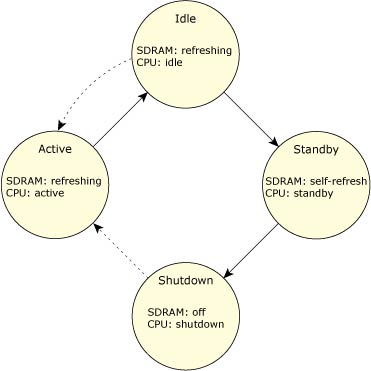
Power savings through power mode transitioning for CPU and memory.
This section describes the OS interfaces for CPU power management:
The sysmgr interface provides a generic, CPU-independent interface for controlling the CPU power mode. This interface is intended to provide a standalone interface that is called by either the power manager, or by a custom power management service in systems that don't use the power manager framework. See "Changing the CPU power mode" section for further details.
The sysmgr interface sysmgr_cpumode() is described in detail in QNX Neutrino Library Reference.
The interface for controlling the CPU mode needs to be exposed to both the power manager, so that it can invoke the underlying kernel support, and custom power management applications in systems that don't use the power manager framework.
The syspage information in <sys/syspage.h> includes:
| Function or structure | Description |
|---|---|
| pminfo_entry | Contains platform-specific power management information |
| init_pminfo() | Initializes the pminfo_entry section |
| power() callout | Validates the supplied mode and performs the specified mode change |
The above functions and datatypes are described in detail in the Building Embedded Systems book.
The information in the pminfo_entry is intended for communication between the power manager (or custom power management implementation) and the low-level BSP support provided by the IPL and startup code.
This section illustrates basic examples of how this structure can be used:
A read-only pointer to this structure is obtained as follows:
struct pminfo_entry *pminfo;

if (_syspage_ptr->pminfo.entry_size != 0) {
   pminfo = SYSPAGE_ENTRY(pminfo);
}
You need, however, a write access -- to set wakeup_pending or modify the managed_storage[] data.
On most CPUs, a writable mapping to the physical memory is created to hold the pminfo_entry structure:
struct pminfo_entry *pminfo;

if (_syspage_ptr->pminfo.entry_size != 0) {
   off64_t paddr;

   if (mem_offset64(SYSPAGE_ENTRY(pminfo), NOFD, sizeof(*pminfo),
      &paddr, 0) == -1) {
   error ...
}
   pminfo = mmap64(0, sizeof(*pminfo), PROT_READ|PROT_WRITE,
      MAP_PHYS|MAP_SHARED, NOFD, paddr);
   if (pminfo == MAP_FAILED) {
   error ...
   }
}
|
This alias mapping does work on certain processors (e.g. ARM) because of its
MMU's virtual cache implementation.
In this case, writable access can only be obtained if the process has I/O
privilege, which allows writable access to the _syspage_ptr memory:
struct pminfo_entry *pminfo;

if (ThreadCtl(_NTO_TCL_IO, 0) == -1) {
   error ...
}
pminfo = SYSPAGE_ENTRY(pminfo);
|
You use the wakeup_pending flag to ensure that a wakeup interrupt is not missed when the system is being placed into a standby mode. Typically, missing this wakeup interrupt would leave the CPU in a standby mode where only a power-on-reset can restart the CPU.
The power manager (or other custom power management implementation) performs the following steps to put the system into a standby mode:
Once in standby, the only way CPU exit that mode is via a configured wakeup interrupt or a hardware reset. Therefore, it is critical that the power() callout behaves correctly in the event the interrupt occurs before the standby mode is entered:
In this case, we assume the callout code can continue to prepare the system for standby, and that the CPU will immediately exit the standby mode because the interrupt is asserted.
On return from the interrupt handling, execution resumes in the callout, and we need to ensure that the callout does not place the CPU into standby.
The wakeup_pending flag is used to handle case (2) above:
You use the following two approaches to implement this:
|
This only works reliably if the driver is using a handler set with InterruptAttach(). This is due to the fact that scheduling is disabled as soon as the kernel call supporting sysmgr_cpumode() is entered. |
In this case, the power manager use InterruptAttach() to attach a handler to the wakeup interrupt and set the flag from that handler. This, however, requires that the power manager knows the (board-specific) interrupt vector(s) used for wakeup events.
The prototype for the power() callout in <sys/syspage.h> is changed to:
struct callout_entry {
   :
   _FPTR(int, power, (struct syspage_entry *, unsigned, _Uint64t *));
   :
};
See the Building Embedded Systems book for detailed information.
You use sysmgr_cpumode(), a generic, CPU-independent interface to control different CPU power modes. This in turn invokes the CPU/platform-specific power() callout to perform the actual work of changing the CPU mode. The following actions are performed:
In order to provide power management support, you need to to control different power modes of the CPU and memory you are using. You write your own custom code to use the sysmgr_cpumode() interface. This is done in cooperation with board-specific startup and IPL software -- to manage different CPU-specific operating modes and board-specific mechanisms for handling standby and wakeup conditions.
The following diagrams depict some transitioning scenarios to provide some design insights:
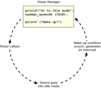
Transitioning to/from Active and Idle using power() callout and interrupt
Note the following for Use Case 1:
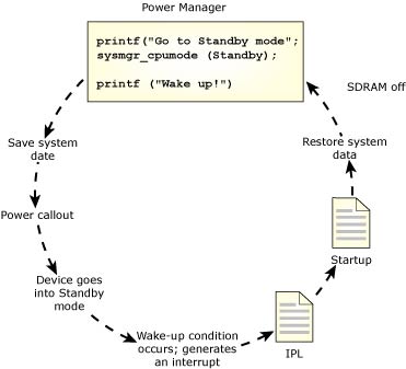
Transitioning from Idle to Standby using power() callout, and Standby to Active using interrupt.
Note the following for Use Case 2:
|
|
|